

|
|
1.INTRODUCTIONBoron nitride nanotubes (BNNTs)1-2 are a type of one-dimensional (1D) nanostructure, which have recently attracted significant interest from the scientific community. Structurally, BNNTs are close analogues of carbon nanotubes (CNTs), but composed of hexagonal B-N bonding networks. CNTs possess purely covalent C-C bonds; by comparison, the B-N bond has partial ionic character due to the differences in electronegativity of boron and nitrogen.3 As a result, BNNTs are electrically insulating with a band gap of ~5 – 6 eV,4-6 while CNTs can be metallic or semiconducting. Research has also demonstrated that BNNTs possess several analogous and compositionally specific properties not seen with their carbon counterparts.7 Specifically, BNNTs exhibit high chemical stability,8 thermal stability (up to 800°C in air),9 excellent thermal conductivity,10 a very high Young's modulus (up to 1.3 TPa),11-12 piezoelectricity,13 the ability to suppress thermal neutron radiation,3 and, as matted fabric, display superhydrophobicity.14-15 These intriguing properties render BNNTs as ideal candidates for a variety of applications such as protective shields/capsules,7 mechanical and/or thermal reinforcements for polymer, ceramic, and metallic composites, self-cleaning materials,16 and biology/medicine.17 They can also be utilized for numerous aerospace applications (spacesuits, habitats, spacecraft, etc.) which require robust materials that can withstand extreme conditions. BNNTs were first predicted4 and later synthesized in 19951 and have continued to gain attention in recent years, evidenced by the increasing number of publications in the field.2, 18 This focus has led to significant advances in the production of BNNTs. Many synthetic methods have already been established including, but not limited to, ball-milling annealing methods,19-20 catalyst-based chemical vapor deposition (CVD),21 arc-discharge,1, 22 laser vaporization, 23-24 plasma-enhanced pulsed laser deposition (PLD),25 and our group's catalyst-free pressurized vapor/condenser method.26 Although some challenges still exist for the synthesis of BNNTs, their increased abundance can allow for fundamental understanding of growth mechanisms, structure-property relationships, and their rational integration into polymer composites and other matrices for real-world applications. In this article, we review and highlight our group's recent progress on BNNTs at NASA Langley Research Center (LaRC), in collaboration with the National Institute of Aerospace (NIA). Comprehensive reviews of other BNNT work can be found elsewhere in the literature.2-3, 18, 27 We will examine a number of key research areas including synthesis and production (Section 2), raw material characterization (Section 3), purification methods to improve the quality of raw material (Section 4), efforts to adequately disperse BNNTs (Section 5), and utilizing dispersed material for the production of composites and mats, both aligned and randomly oriented (Section 6). Additionally, we present our modeling results on 1) the piezoelectric properties of BNNTs and 2) laser vaporization and plume chemistry of our production chamber in combination with optical diagnostic techniques, which are employed to validate our modeling results and improve our materials production (Section 7). Subsequently, we explore the properties and applications of BNNTs, among other research that BNNTs enable (Section 8). Lastly, a summary and outlook on the potential impact of BNNT research is provided in Section 9. 2.SYNTHESIS AND PRODUCTIONTechniques to grow BNNTs can be divided into two broad categories, low temperature and high temperature. In the low temperature synthesis method, the operating temperatures are between 600 and 1700°C, well below the vaporization temperature of pure boron (over 4000°C, depending on ambient pressure). The two common low temperature synthesis methods are ball-milling and chemical vapor deposition (CVD). Both of these techniques require catalysts but are capable of producing hundreds of milligrams to grams of BNNTs. Typically, BNNTs produced by CVD and ball-milling are multi-walled and possess large diameters (~ 50 nm). In addition, these tubes frequently suffer from faceted/wavy walls, elbows, and herringbone/bamboo-like morphologies. The second category is the high temperature synthesis method, which involves vaporizing elemental boron or a boron nitride target. The vaporized boron then reacts with nitrogen and condenses into BNNT. There are two high temperature synthesis techniques, arc-discharge and laser heating (or ablation) methods. These methods both produce high quality BNNTs (few defects and small numbers of walls) that are very thin (~ 5 nm). Similar to the low temperature methods, the arc-discharge requires the use of catalysts and generates small diameter nanotubes with low aspect ratios. The high temperature-pressure (HTP) method of synthesis, known as the pressurized-vapor/condenser method,26, 28 is currently being pursued by NASA and the NIA and is capable of producing high-quality, high aspect ratio BNNTs. NASA's BNNT production laboratory (Figures 1A, B) consists of a pressure vessel, boron target, and a heat source. The boron target is located inside a vessel pressurized to 1.38 MPa (200 psi) with research grade N2. When the boron is heated to its boiling point (~ 4000 K) by a commercial grade cutting laser, an ascending plume of vapor is produced which interacts with the pressurized nitrogen on an atomic level to produce BNNTs (Figure 1C). NASA's BNNT production typically produces 20 milligrams (mg) of material an hour and runs a total of 12 to 20 hours per week, averaging 4 hours per run. The material generated is utilized for purification and dispersion studies, composite fabrication, and various other experimental studies. Figure 1.(A) NASA LaRC's BNNT production lab, (B) synthesis chamber, and (C) representative TEM image of BNNTs grown at NASA LaRC.  Currently the optimal growth conditions for producing high quality, high quantity BNNTs are not completely understood. The National Institute of Aerospace (NIA), in collaboration with NASA, has set up a dedicated BNNT laboratory to study BNNT nucleation and growth under various conditions (Figure 2). The new NIA BNNT laboratory has a high pressure synthesis chamber with a state-of-the-art 2.5 kW diffusion cooled CO2 slab laser, offering higher Gaussian beam quality (k-factor > 0.8 (perfect Gaussian = 1)) and hence, better focusing ability than the laser at the NASA BNNT laboratory. The custom-designed 6.89 MPa (1000 psi) reaction chamber (Figure 2A) was designed to allow an easy access to the inside of the chamber. This includes viewing ports on three sides to enable various visualization techniques along with in situ spectroscopy studies during synthesis. This chamber can be modified to explore various methods to increase yield and quality, such as varying the pressure, rotating the chamber, and using different collector geometries. Figure 2.(A) New NIA BNNT Science Rig in a safety hutch with a laser protection window, (B) white spider web like BNNT grown for 10 seconds, and (C) corresponding TEM micrograph.  Additionally, optical in situ diagnostics can be performed during the synthesis and the data can be utilized in modeling codes to improve the energy coupling efficiency between the laser and boron target to maximize the production of high-quality BNNT. Emission spectroscopy, pyrometry, and high-speed photography (shadowgraphs) have already been implemented in the NASA BNNT synthesis system successfully, which will be adapted to the new NIA BNNT chamber with NASA colleagues. Future spectroscopy studies may include PLIF (Planar Laser Induced Fluorescence), CARS (Coherent Anti-Stokes Raman Spectroscopy), Raman, Rayleigh/Mie scattering, along with absorption spectroscopy which will aid in the understanding of the chemistry and flow physics involved in BNNT generation. The in situ diagnostic techniques will help us to understand how the growth process changes under different operating conditions. The optical diagnostic results can further improve computational modeling/simulation (Section 7.2), which will aid in iteratively adjusting the operating conditions for optimized production rates and high-quality material. Using this custom-made chamber and stable diffusion cooled slab laser, NIA has been successfully synthesizing high-quality BNNTs since the first run in July 2013. The quality and synthesis yield of NIA BNNTs can be further enhanced and optimized by controlling key parameters with the custom designed chamber. Even at a chamber pressure of 1.00 MPa (145 psi) and laser power of 1 kW, the NIA BNNT chamber produced BNNTs equivalent in quality to BNNTs produced at 1.38 MPa (200 psi) and 1 kW with the NASA chamber, as determined from transmission electron microscopy (TEM) characterization. Figure 2B shows white spider web-like BNNT grown for 10 seconds at the very first test run without optimization and corresponding TEM image of the as-grown BNNTs is shown in Figure 2C. Most of the nanotubes are long, thin (single to few walls), and highly crystalline with relatively few impurities, which is very promising for the optimization study. 3.CHARACTERIZATIONDuring synthesis, the growth mechanism and the morphology of BNNTs are affected by several experimental parameters such as initial chamber pressure, growth temperature, laser focus, and the thermal chemistry of the boron and nitrogen sources. In addition, the formation of BNNTs is largely influenced by the growth mechanism in which nucleation/propagation can occur via root-growth or tip-growth. The lack of understanding of the growth mechanism arises mainly from an absence of experimental evidence. Coupled with the small size of the nanotubes and the relatively small quantities of material available, high-resolution TEM (HRTEM) is the most suitable analysis technique. Both crystallographic and morphologic data can be obtained and correlated with changes in experimental parameters to 1) study growth mechanism and 2) optimize the growth environment of BNNTs. Spatially resolved electron energy loss spectroscopy (EELS) can often be obtained in conjunction with HRTEM which can be utilized to determine band gap energy levels. The data can be used to corroborate or invalidate current theoretical studies4-5 on the band gap sensitivity to the structure of BNNTs. The as-grown BNNT material typically range anywhere from grey to white in appearance. These products consist of an inhomogeneous mixture of nanotubes and nanoparticles as shown in Figure 3A. The nanotubes are either isolated or organized in small bundles (2 – 10 tubes), with lengths ranging from several hundreds of nanometers up to several microns among the bundled and entangled networks. In the inset of Figure 3A, the HRTEM image reveals a straight-walled tubular structure with clearly distinguishable layers in the multi-walled nanotubes. An additional TEM image (Figure 3B) demonstrates that the size, shape, and structure of nanoparticle impurities (boron or BN) are very heterogeneous. They can be attached at the nanotubes, isolated, or encapsulated in BN shells in the case of boron. The h-BN nanoparticles have been observed to range from 50 nm to 200 nm in size, while the BN-encapsulated boron nanoparticles are found in the 10 – 20 nm range (Figure 3B, red arrow) or > 100 nm (Figure 3B, yellow arrow). Analyzing the boron nanoparticles was of significant interest as they are intimately involved in the growth mechanism of the nanotubes. The encaged particles are nearly spherical in shape whereas the h-BN shells wrapping them form polygons, as attested by the examples shown in the HRTEM images (Figure 3C and D) for the different sized boron particles. Combining microscopy with in situ diagnostics and modeling studies will allow us to synthesize BNNTs with minimum impurities or predominately generate one type of impurity by controlling the experimental parameters for specific demands. Figure 3.Representative TEM images of (A) BNNTs with HRTEM inset of a double-walled and 10-walled BNNT, (B) BNNTs and impurity nanoparticle species, (C) > 200 nm h-BN encapsulated B particle, and (D) a < 10 nm h-BN encapsulated B nanoparticle. (E) EELS spectrum line across a BNNT. The K-edges of boron (~ 189eV) and nitrogen (~ 400eV) can be seen in these spectra showing they form the BN frame of the nanotube and are uniformly distributed. (F) Band gap measurement for a 3-wall BNNT and 6-wall BNNT from low energy EELS spectra.  The band gap of the as-synthesized BNNTs was confirmed by EELS. As shown in Figure 3E, sharp boron and nitrogen K-edge bands were detected, which are composed of both π* and σ* peaks that are typical for sp2 bonded BN networks with a boron to nitrogen ratio equal to unity (1:1).4 The optical band gap in individual nanotubes is measured at the intersection between the flat background and the line fitting the slope of the first peak of the low energy EELS spectra,29 as shown in Figure 3F. For all investigated nanotubes (diameter ranging from 3 to 6 nm and number of layers of 3 and 6), the value of the optical gap is found to be 5.74 eV, independent of diameter and wall number, which is very close to that of bulk h-BN. In addition to TEM studies, BNNTs and BNNT mats (see Section 6) prepared at NASA LaRC were also probed with a Brunauer-Emmett-Teller (BET) surface analysis system to gather information on dispersion quality and surface area. The BET model was adopted to calculate the surface area in the mesoporous range (2 – 50 nm) based on the nitrogen gas adsorption of the samples. The analysis can provide their specific surface area (m2/g), which can be used to evaluate the quality of each sample with respect to dispersion, debundling, aggregation, and presence of impurities. For example, as-synthesized BNNTs possessed specific surface areas in the range of 200 – 300 m2/g. Preliminary results demonstrate that, upon purification with nitric acid (see Section 4), the purified BNNTs exhibit increased surface area as compared to the raw BNNTs. The increased surface area can potentially be attributed to the removal of boron nanoparticles and exfoliation of BNNTs during the acid treatment. The removal of impurity species and the debundling of BNNTs is critical for structural applications since impurities will serve as failure points during mechanical testing, degrading the structural properties. As such, the combination of electron microscopy and surface area analyses are effective for gaining qualitative and quantitative data on BNNTs. 4.PURIFICATION METHODSAs demonstrated in Section 3, the HTP method generates small highly-crystalline, small diameter BNNTs but often contains impurities that need to be removed, such as boron nanoparticles encapsulated in a BN shell, amorphous and crystalline BN, as well as BN nanoparticles. The presence of these impurities can potentially degrade the advantageous properties of the BNNTs, although additional experiments are needed to compare the properties of raw and purified BNNTs. For example, impurities can act as defect sites at which failure can occur under mechanical testing. Hence, purification may be a critical step for fundamental and applied research. Therefore, we have investigated a variety of purification methods to determine the optimum approach to generating compositionally and morphologically pure BNNTs. Currently, we are exploring three different approaches, namely acid treatment, thermal purification and surfactant separation, with the objective of selectively removing certain impurities from as-synthesized BNNTs. For example, acid treatment is aimed at the removal of boron nanoparticles, as boron is well known to oxidize in the presence of nitric acid to boric acid which is water-soluble. Heat treatment as a purification approach is being explored as BNNTs are stable in air up to 800°C. The goal is to oxidize the boron nanoparticles and subsequently remove the water-soluble boron oxide (B2O3) formed during the heating process. Alternatively, heating boron in a nitrogen atmosphere generates BN, which can also be oxidized in air, forming B2O3.30 Lastly, the surfactant purification approach utilizes surface-active agents, or surfactants, to influence the interfacial tension of the various species in the BNNT sample, enabling the removal of impurities. A similar approach has already been successfully utilized for CNTs.31 Studies have already begun for determining the optimum surfactant(s) for the removal of all impurities including boron nanoparticles and undesirable BN species. This approach to purifying the nanotubes is the least destructive and therefore the preferred method. Acid treatment of boron nitride nanotubes via nitric acid reflux has been extensively explored. The nitric acid is proposed to penetrate the BN shell that encapsulates the boron nanoparticle (Figure 4A), resulting in a water-soluble impurity. Although scanning electron microscopy (SEM) analysis demonstrates that the nitric acid successfully removes the boron nanoparticles, leaving behind a hollow BN shell (Figure 4B), the BNNTs were found to be significantly damaged during the treatment. These observations are similar to nitric acid treatment on CNTs, which has been previously shown to remove metal catalyst particles at the expense of the nanotubes.32 Furthermore, structural composites and mats fabricated from purified BNNTs possessed little to no integrity as a result of the degradation of the nanotubes during acid purification. Figure 4.SEM images of (A) raw BNNTs showing the presence of large boron nanoparticles and (B) BNNTs after acid treatment demonstrating the removal of B and the presence of hollow h-BN shells. The insets are the TEM images of boron nanoparticles (A) and hollow h-BN shells (B).  As the acid treatment of BNNTs is investigated further, other approaches are needed to remove non-tubular BN impurities from as-grown BNNTs. Along with thermal and surfactant purification, kinetic purification will be investigated as a purification method for BNNT. The kinetic purification approach exploits the measured densities of the BNNTs and the impurities in a process to remove the undesirable contents of the sample. This method will include using sonication and centrifugation in various ways to achieve the purification of BNNT. These various purification approaches will be utilized to develop an optimal method of purification to generate high-quality, pure BNNTs which will enable fundamental studies, structural nanocomposites, and various other applications. 5.DISPERSIONSimilar to CNTs, one of the critical issues in BNNT research is dispersion of individual nanotubes in solution, enabling further processing and handling.33 Poor dispersion, aggregation, and bundling are often detrimental to intrinsic properties, yielding significantly lower values than theoretically predicted. For example, poor dispersion can prevent efficient load transfer from the matrix to nanotube reinforcements of a composite material, which impairs the mechanical properties of the structure. Effective dispersion and understanding the relationship between matrix chemistry, processing methods, and the resulting physical properties are necessary steps towards tailoring the performance of nanocomposite materials. Hence, the ability to manipulate BNNTs in uniform, homogenous solutions enables researchers to harness their unique, advantageous properties facilitating fundamental research. Fabricating nanocomposites, by combining nanomaterials within a hosting material, is a potential method to produce macroscopic material systems that benefit from nanosized constituents. However, orderly distribution of nanosized constituents has proven to be an intrinsic obstacle, and is complicated by bundling caused by attractive intermolecular forces between the nanomaterials themselves. Although extensive literature is available on the exfoliation and dispersion of CNTs,34 many of these methods alter or damage the sp2 nature of the nanotube surface altering their native properties. For example, high-power sonication has been shown to drastically shorten tube length35, while chemical functionalization methods directly modify the surface structure. Exploration on BNNT dispersion and exfoliation have been limited to sonication in conjunction with 1) individual solvents or 2) functionalization by polymers, surfactants, and other biomolecules.36-43 The objective was to develop a means of uniformly dispersing BNNTs without the need for functionalization or sonication in order to preserve the high aspect ratios of the nanotubes and their sp2 nature, which is responsible for their extraordinary properties. Solvents with relatively good BNNT dispersion ability can be determined by comparison of the thermodynamic Hansen parameters. The Hansen solubility parameters for dispersion, polar, and hydrogen bonding, represent the intermolecular interactions contributing to the solubility of BNNT into a solvent. The solubility parameters can be plotted to determine a three-dimensional volume encompassing solvents that effectively disperse BNNT. Solubility theory has been utilized to determine solvent mixtures for dispersing single-walled CNTs44 and graphene.45 It has been shown that solvents tend to dissolve solutes with parameter values similar to their own, which can be exploited to predict and tailor optimal solvent combinations. Co-solvents were investigated as a means to enhance the solubility as compared to a single solvent.46 This method of dissolving the BNNT in a co-solvent without sonication or functionalization preserves the intrinsic BNNT properties. The approach of matching solubility parameters between materials is commonly utilized in other fields (e.g. polymer, paint, and art conservation) in order to selectively dissolve components while decreasing the need for toxic and costly solvents that can be mimicked with a co-solvent combination. We have attempted to identify the region using the graphical method44 from observations of solvent and co-solvent interactions with BNNT, since the solubility parameters for BNNT are unknown. By ranking solvents based on their dispersion strength, a solubility region for BNNTs was estimated. In this way, several candidate solvent and co-solvent systems were identified for subsequent testing to verify the region and save resources by eliminating incompatible combinations. Based on observations of this dispersion study, highly polar, aprotic solvents disperse bulk BNNT materials most effectively with or without sonication. Such solvents tend to be high boiling and define a broad solubility region for BNNT in terms of solubility parameters. The efficacy of each solvent can be compared to each other and to co-solvents designed to mimic the best known solvents to disperse BNNT. One successful co-solvent system designed to disperse BNNT is composed of two solvents. Solvent A is a highly polar, aprotic solvent (e.g. DMF, DMSO, NMF, etc.), while Solvent B, which is protic, does not lie within the BNNT solubility region (e.g. water, methanol, IPA, etc.). Both solvents are incorporated into a co-solvent ranging in ratios from 80:20 to 50:50 for Solvent A:Solvent B. The resulting solubility parameters are averaged from those of the individual constituents based on the ratio of the two solvents. Thus, by designing and testing co-solvent systems, one can further narrow the BNNT solubility region in finer increments than with pristine solvents alone. This approach can also be used to determine the usefulness of choosing solvents with certain chemical and structural properties to aid in dispersion, since the solubility parameters incorporate these traits. For example, the BNNT solubility region resides at a low hydrogen bonding range, implying that BNNT is hydrophobic, and does not interact well with solvents containing the hydroxyl group which includes alcohols. This verifies the hydrophobic behavior of BNNT, since water lies far outside the determined solubility region. These results are promising, though additional studies are still needed to determine the best solvent(s) and/or co-solvent system for BNNT dispersion. 6.STRUCTURAL COMPOSITESPreviously, we demonstrated that BNNT yarns could be spun directly from as-grown BNNTs which may have potential as structural reinforcements for composite materials.26 BNNTs are also highly desirable for nanocomposites as a result of their excellent thermal, chemical, and electrical properties. Hence, BNNTs are capable of fulfilling multiple roles (e.g. structural reinforcement, neutron radiation shield, electrical insulator, textile reinforcement, and mechanical sensors) within polymeric, ceramic, and even metal matrices, generating light-weight materials which are appealing for a variety of space and aerospace applications. Although the literature on BNNT composites is limited, materials up to 10 wt% have already been reported, which show significant improvements in elastic modulus and thermal conductivity over the neat matrix.27 For example, a 1 wt% BNNT-polystyrene (PS) composite displayed a 21% increase in the elastic modulus of PS, while a 10 wt% BNNT-poly(methyl methacrylate) (PMMA) composite displayed a 3-fold increase in the thermal conductivity of PMMA.27 The initial approach to fabricating BNNT composites focused on generating mats (Figure 5A) through vacuum filtration of a dispersed solution of BNNTs, which would then be subsequently infiltrated with an epoxy or polymer. Although preliminary results showed some success for generating structural materials, the process was not easily replicated, which may be a result of impurity species present in the as-synthesized material. Mats produced from acid-purified BNNTs (see Section 4) were observed to have little or no structural integrity. Similar behavior was also noted for mats generated from heavily sonicated BNNT solutions. Figure 5.(A) Example of a BNNT mat fabricated by vacuum filtration, (B) Image of small scale BNNT-CP2 composite samples containing 33 wt%, 50 wt%, and 67 wt% BNNT (from left to right), and (C) image of a BNNT-epoxy composite containing 10 wt% BNNT. The sample shown in (C) measures 5 mm by 16 mm in width and length, respectively.  Recently, we developed a new method for fabricating high weight percent (wt%) nanocomposites materials which is capable of locking in the dispersed state of the nanotubes. This is critical for realizing the true potential of the BNNTs. Utilizing this method, composite samples containing up to 75 wt% BNNT with various polymers such as polyvinyl alcohol (PVA), polyurethane (PU), PMMA, and LaRC™-CP2 were generated. Some examples of the composites are shown in Figure 5B for BNNT-CP2 samples at 33, 50, and 67 wt% BNNT. Additional work on BNNT-epoxy composites has also shown promise; a 10 wt% BNNT-epoxy composite (Figure 5C) was generated with a two-component epoxy. The estimated void content based on theoretical density of BNNT was less than 2%. Details on the fabrication process for polymer and epoxy composites will be available in future publications. The composites can be further consolidated by pressing during the drying process or by subsequent hot-pressing. Preliminary mechanical tests on small scale polymer composites have demonstrated an increase in the storage modulus by two orders of magnitude over the pure PU matrix with the incorporation of BNNTs up to 67 wt%. An increase in both the glass transition temperature and melting point above those of the neat polymer by up to 35°C was observed with an increase the wt% of BNNTs for PAN, PU, and CP2. Although preliminary, these results indicate that contact between the randomly-oriented nanotubes and the polymer is maintained during the fabrication process. Subsequent scaling-up of the composite size will enable additional standardized mechanical testing (e.g. tensile, compression, wear) which will further elucidate the potential of BNNTs as structural reinforcement. While the random-oriented BNNT composites demonstrate potential for structural and mechanical reinforcement, generating composite materials with aligned BNNTs is also critical in terms of achieving the best properties, which has been previously demonstrated for BNNT-PVA composites.47 Thus, we have also explored various techniques to orient and align BNNTs including interfacial polymerization, fiber drawing/spinning, hot-press molding, melt extrusion, and self-assembly methods using surfactants, block copolymers, and liquid crystal polymers. This can be further extended to explore the subsequent removal of the polymer matrix to generate aligned BNNT structures for other applications. Another promising alignment method is the utilization of interfacial polymerization. Here, accelerated step growth kinetics occurs at an interface between two immiscible liquids where each solution contains different monomers. Candidate polymer systems include polyamides, polyesters, polycarbonates, and polyurethanes. In a recent study nylon 6,10 was utilized to fabricate aligned BNNT nanocomposite materials via interfacial polymerization of the polyamide and fiber spinning process. BNNT-polyamide nanocomposite fibers, 100 – 500 μm wide and < 100 μm thick, were successfully obtained via a continuous spinning process. Hence, this method is advantageous for BNNT alignment due to rapid entrapment of BNNTs at the viscous interface followed by the continuous extraction, of the swollen polymer interfacial membrane, aligning the polymer molecules and the nanotubes along the fiber axis. Morphological characterization using HRSEM suggests that the interfacial polymerization process with BNNT dispersion enabled BNNTs to be embedded in polyamide fibers oriented parallel to the spinning direction, though further analysis is needed to quantify these observations. 7.MODELING AND DIAGNOSTICS7.1Molecular Dynamic Modeling of Piezoelectric BNNTsBNNTs have been shown to exhibit electroactive behavior in response to mechanical deformation,48 which is highly advantageous for sensor, actuator, and energy applications.49 Although the intrinsic piezoelectricity of BNNTs is well established, the nature of this phenomenon is not well understood. In order to probe the effects of atomic scale structural changes on the observed electronic behavior, we have developed an empirical model for replicating the piezoelectric properties of BNNTs. To improve upon existing computational approaches, a novel geometry-dependent polarization term was added to the B-N interatomic potential currently utilized for neutral BNNTs.50 This additional term emulates the dipole polarization of the B-N bond under strain to accurately reproduce the piezoelectric behavior of BNNTs. The model predictions for the piezoelectric coefficients (e11 and e14) of single-walled BNNTs (Figure 6A) under uniaxial tension and twist along the nanotube axis were computationally verified against previous ab-initio and tight-binding calculations reported by Sai and Mele.49 A good qualitative and quantitative agreement between the tight-binding and our molecular dynamics (MD) model was achieved (Figure 6B), although minor differences were noted for nanotubes of very small diameter (< 1 nm) as well as armchair tubes polarized in twist which can be ascribed to the structural buckling that occurs in the MD simulations. Interestingly, a weak spontaneous polarization was predicted for unloaded nanotubes, which was found to increase with decreasing diameter. While spontaneous polarization is expected for BNNTs, there is no consensus within the field on its existence. Hence, more experimental data is needed to address and substantiate these findings. The modeling results indicate that the developed model works well for BNNTs over the entire range of chiral angles (θ) from armchair (θ = 0°) to zig-zag nanotubes (θ = 30°) and functions under both tensile and twist loading. This simplified and efficient approach can be utilized for molecular dynamics and Monte Carlo simulations on larger scale systems inaccessible by quantum mechanics based computations. As such, this model can serve as a foundation for atomic-level modeling of the electroactive properties of large systems of BNNTs, BNNT composites, and other structures such as planar h-BN. Figure 6.(A) A simulated single-walled (9,0) zig-zag BNNT system with green and blue sphere representing B and N atoms, respectively. (B) Piezoelectric coefficients, e11, and e14, for (n,0) and (n,n) BNNTs, respectively, obtained from the molecular dynamics simulations, scaled by the nanotube circumference, C, and plotted versus the inverse square of the radius given as 1/n2. 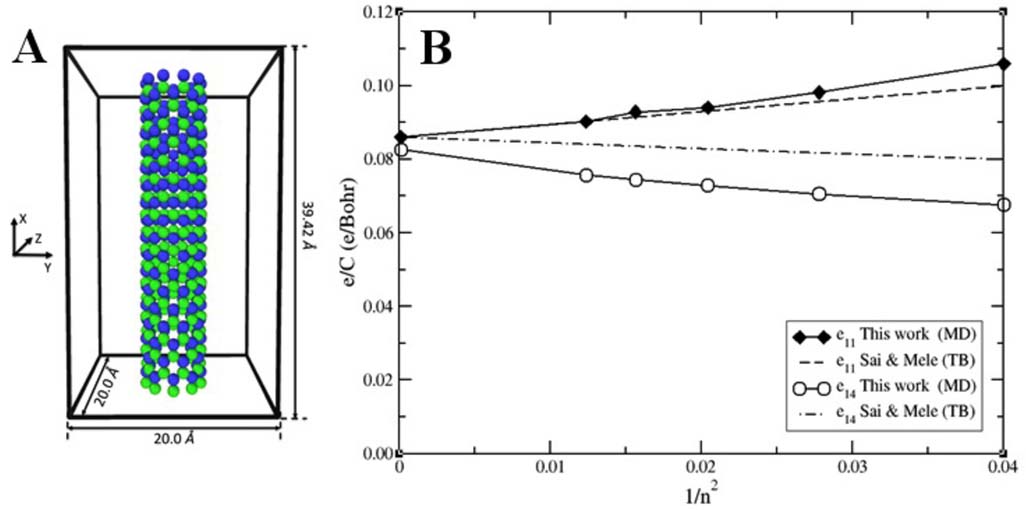 7.2Modeling of Laser Vaporization and Plume ChemistryThree goals for our BNNT modeling program are to: (1) define the environment in which nanotubes now grow; (2) define the optimum environment for growing BNNTs; and (3) explore modifications to the BNNT chamber by simulation to promote the optimum growth environment. In essence these goals address three fundamental questions. Where are we now? Where do we need to go? How do we get there? Defining the current growth environment has received the most attention. A hypersonic flow simulation code, Langley Aerothermodynamic Upwind Relaxation Algorithm (LAURA), has capabilities to model environments over planetary entry vehicles including effects of coupled radiation and ablation. This code was modified to simulate effects of radiative heating (laser) on a boron surface in a high-pressure nitrogen atmosphere. Thermochemical models for a boron-nitrogen system and inclusion of gravitational forces (buoyancy) were added to LAURA to implement the simulations. A parametric study51 on a simplified geometry documented the flow rate of BN and B2 in a plume rising from the irradiated, molten boron ball. Parameter variation included pressure, laser power, and atmospheric dilution with noble gases (He, Ar). A key result shows that significant dissociation of N2 near the boron droplet surface occurs only when higher pressures raise the boiling point of boron. As boron vaporizes and diffuses through the dissociated nitrogen BN molecules are formed. Depending on the kinetic models employed, a supersaturated concentration of BN in the rising, cooling plume is available to feed nucleation of BNNTs. As pressures continue to rise for a fixed laser power input, the dissociation of nitrogen is suppressed and mass flow rates of BN slowly diminish. Defining the optimum environment requires understanding the nucleation mechanisms for growing BNNTs. Here a fundamental question regarding the conditions that promote growth of long nanotubes as opposed to more amorphous aggregations of boron and BN solids. Two mechanisms are postulated. The first, a tip-growth mechanism, would involve rapid nucleation of a nanotube from a supersaturated BN plume that continues until the tip closes or the BN reservoir in the plume is depleted. The second, a root-rowth mechanism23, 52 would involve growth of the crystal from a “micro-droplet” of boron. This mechanism is suggested from TEM observations in which nanotubes are often connected to a hardened droplet of boron. These micro-droplets may be formed from condensation as gaseous boron rises and cools, or they may be ejected from the surface of the large, irradiated boron droplet hanging from the fiber bundle. This ejection mechanism is proposed from the observation of the ejection of material formed when the hanging boron droplet is jostled by the mechanical advancement of the receding fiber bundle back into the path of the laser. In this mechanism, BN molecules are formed or adsorbed on the micro-droplet surface. As the micro-droplet rises and cools within the plume the crystal is drawn out from the reservoir of BN building blocks along the surface. Micro-droplet radius and cooling rates would be key parameters affecting nanotube length in this scenario. Options for molecular dynamics scale modeling of these potential mechanisms are currently being evaluated. Optimizing production rates based on knowledge of the actual nucleation physics will be aided by simulation of the plume environment. For example, consider the temperature environment in the rising plume from the irradiated droplet presented in Figure 7. The temperature scale starts at 2600 K, the approximate melting point of boron at 1.38 MPa (200 psig), in order to highlight distinct temperature zones in the plume. Assuming both axisymmetric flow and buoyancy effects, for simplification, the plume rises vertically in the closed chamber. Atomic nitrogen is formed in the red zone near the droplet surface. Rising micro-droplets, if any, will tend to cool and solidify as they rise above the green and cyan zones in the plume and give up latent heat from their interior. Considering the effects associated with a cooling jet of nitrogen directed from below the droplet, this could promote recirculation of micro-droplets through the hot, red zone rich in nitrogen and BN for adsorption. A cooling jet in association with higher laser power could extend the length and time of residence in the green zone, while stabilizing the hanging droplet under conditions of larger energy input. Other scenarios could be envisioned, and simulation will guide how they may be implemented to obtain optimum environments as identified by both experiment and molecular dynamics simulations. 7.3In situ DiagnosticsQualitative and quantitative data are needed to develop a detailed understanding of the chemistry and the flow physics of nanotube fabrication, and to study how this process changes under different operating conditions. Nonintrusive optical measurement techniques can be used to improve and validate simulation and modeling of the fabrication process, as well as the nanotube growth process. A variety of measurements are needed such as the gas composition, gas temperature, and the temperature of the boron target in its molten state. For example, the temperature of the boron target provides an important validation point and/or boundary condition for the computations. By utilizing these optical measurement techniques, additional information will be available to optimize the synthesis of BNNTs, improve material properties, and increase production rates. Five different optical measurement technologies have been investigated: 1) high speed camera imagery, 2) shadowgraph flow visualization, 3) optical pyrometry, 4) planar laser-induced fluorescence (PLIF), and 5) coherent anti-Stoked Raman spectroscopy (CARS). Both 1 and 2 are qualitative methods and their results are summarized below. The latter three techniques (3 through 5) are semi-quantitative or quantitative and currently under development; the rationale for using these methods is briefly discussed. A high speed color Phantom v9.1 camera (with 1,632 x 1,200 pixels) capable of framing at over 1 kHz rates was used with a high magnification setup (nearly 1:1 imaging, using a 200 mm focal length lens with several macro rings) in the NASA BNNT rig to provide close-up images (Figure 8) of the molten boron ball and the BNNT fibrils that were being produced. In Figure 8A, the top left corner shows the bundle of boron wires (dia ~ 0.32 cm) that compose the boron feedstock under normal operating conditions. The CO2 laser melts the boron wires and surface tension holds the molten ball of boron to the bundle. The brightness in this image increases with temperature (although the emissivity - and thus brightness - of solid phase boron is about a factor of two higher than the liquid phase).53 Consequently, the hottest part of the ball is at the top-right corner where the laser is incident upon the ball while the cooling along the feedstock is evident from the decreased intensity along the feedstock. The sudden increase in brightness indicated by the black arrow is likely caused by the interface between the liquid-phase boron (to the right of the interface) and a crust of solid phase boron (to the left). Figure 8.Still frames from the high-speed camera showing (A) the boron target and molten ball under normal operating conditions, (B) the target and molten ball with a misaligned configuation, (C) rising fibrils collecting and adding to others on the condensor wire, and (D) fibrils missing the condenser wire (denoted by the blue line segments).  By contrast, Figure 8B shows the boron target with the laser misaligned wherein the round-shaped exposed liquid surface is far from the center of the bundle of boron rods. Such information can be used to more carefully align the boron target and laser to optimize production. Figure 8C shows material rising up from the molten ball at the bottom of the picture (not shown) and being captured on the condenser wire forming BNNT fibrils, though in some instances the fibrils miss the condenser wire (Figure 8D). Based on these images, it appears that the nanotubes are being formed in the gas phase prior to condensing on the wire. The use of a shadowgraph system to visualize both the molten boron ball and the gaseous flow around the ball during operation at the NIA BNNT lab (Figure 9) was an improvement. A continuous white-light source was used to illuminate a conventional54 lens-based shadowgraph system having a 100 mm diameter, 500 mm focal length lenses. A beam splitter was used to allow two different cameras to visualize the resulting shadowgraph images: a low-resolution greyscale 30 frames per second video camera (Hitachi KPM1 with 768 x 493 pixels) that could be continuously recorded and the same type of color Phantom v9.1 high speed camera were set to record the shadowgraphy, which could be recorded in short (1 – 2 s) bursts. The natural luminosity of the hot molten ball allows it to be directly imaged by the optics while the purple sections of the image show the shadowgraph, which is sensitive to density gradients in the flow. The high speed camera tracked the temporal dynamics of the plume of hot gas rising from the molten boron ball at high pressures above 1.38 MPa (200 psi). Generally, the plume was steady and narrow, rising above the ball and eventually becoming unsteady and oscillatory as shown in Figure 9A. The left side of each image shows fibrils attached to the feedstock holder. In some cases, some particulates were ejected from the molten boron ball at the 60° (Figure 9B, blue arrow) and 210° (Figure 9B, yellow arrow) positions. The unsteady nature of the plume suggests that the computational simulations should include a turbulence factor as opposed to a steady-state solution at high pressures. Another extension of the high speed imagery is to perform pyrometry which utilizes either the intensity or spectrum of emitted light to determine temperature of a surface. Currently, both single-wavelength and two-wavelength pyrometry are being explored in conjunction with a high-speed camera to ascertain the quantitative temperature and time-resolve the temperature distribution of the molten boron ball. Figure 9.Shadowgraph of the NIA BNNT synthesis chamber (A) without and (B) with mass ejection from the molten boron ball. In (A), as-grown BNNTs (1), the plume (2), boron feedstock (3), and molten boron ball (4) are highlighted for reference. In (B), the mass ejection at 60° and 210° are denoted with the blue and yellow arrows, respectively.  Further work is ongoing to develop and apply PLIF and CARS to the NIA BNNT chamber. PLIF involves using a planar laser sheet to excite fluorescence, collected by a camera, of a specific species within the flow. CARS involves crossing and focusing three pulsed laser beams to probe the Raman resonances of any species present at crossing point of the lasers. A nonlinear Raman interaction causes a fourth beam to be generated and analysis of this fourth beam allows determination of temperature and concentration. The species expected to be present in the chamber include B2, B, BN, N, and N2, which can potentially be probed with PLIF or CARS to gain further insight into the growth mechanism of BNNTs synthesized by the HTP method. 8.APPLICATIONS BNNTs ENABLE8.1Electroactive MaterialsNakhmanson's theoretical analysis predicted that the piezoelectric coefficient of BNNTs can be higher than that of poly(vinylidene fluoride-trifluoroethyene) P(VDF-TrFE).13 The piezoelectric properties of BNNTs or BNNT composites, however, have not been reported experimentally yet. A BNNT polyimide composite film actuator for piezoelectric characterization was fabricated by a filtering method.55-56 While the sample was under an AC electric field of 1Hz, in-plane strain (S13) was measured using a fiber optics. The strain (S13) of the sample appears as a superposed curve of linear and nonlinear strains as a function of frequency. The superposed curve was de-convoluted to a linear response and a nonlinear response. The linear response seems to be originated from the piezoelectric property of the BNNT active layer (Figure 10). From linear fitting of the data, the piezoelectric coefficient, d13, was estimated to be 14 pm/V. This is comparable to the values of commercially available piezoelectric polymers such as poly(vinylidene fluoride) (PVDF). The nonlinear response showed a quadratic increase with increasing applied electric field, indicating that the mechanism of this strain is mainly an electrostrictive response, which is several orders of magnitude higher than those of commercially available electrostrictive polyurethane materials. These results suggest that BNNT-based electroactive materials may be used for electromechanical energy conversion devices. 8.2Radiation ShieldingThe space environment contains major hazards, one of which is space radiation. The space radiation consists mainly of electrons and protons, solar energetic particles (SEP), and galactic cosmic radiation (GCR). The GCR is composed primarily of nuclei (fully ionized atoms) plus a small contribution (~2%) from electrons and positrons. GCR particles with high atomic number (Z > 10) and high energy (E > 100 GeV) are also present.11 Additional radiation hazards come from neutrons and gamma rays produced in nuclear collisions and from X-rays arising after Coulomb interactions. Neutrons are produced as secondary radiation when the GCR and SEP interact with the walls and contents of the space structure (e.g. vehicle, lander, habitat, rover, or spacesuit), planetary atmospheres, and also with the regolith on the surfaces of the Moon, planets, or asteroids. Hydrogen, with the highest charge-to-mass ratio of any element, provides the best shielding against thermal neutons.12 As a shield of pure hydrogen is not practicable, hydrogen-containing materials make the most suitable candidates for shielding. The BNNTs are made up entirely of low Z atoms, boron (5) and nitrogen (7). Boron and nitrogen are larger than hydrogen (1), but they are still small. BNNTs can theoretically be processed into structural components and utilized for load-bearing structures; they are also attractive candidates for hydrogen storage. Boron has one of the largest neutron absorption cross sections of all the elements of the periodic table, and nitrogen has a larger neutron absorption cross section than carbon. The neutron absorption cross section for the isotope B10 is 3835 barns, so enriching BNNT or BN with B10 would result in enhanced protection against thermal neutrons, especially if enriched with a sufficient amount of hydrogen. Since neutron radiation is known to be damaging to human organs and tissue, the possibilities are worth exploring for using BNNTs for radiation shielding structural materials. The computer code used for the computational modeling of materials was OLTARIS (On-Line Tool for the Assessment of Radiation in Space)58 which uses the HZETRN (high charge and energy transport) code developed at the NASA Langley Research Center. The OLTARIS modeling study indicates that hydrogen containing BNNTs may offer excellent shielding effectiveness against GCR and SEP. When one considers wall thicknesses and forms of materials that could actually be used to build spacecraft, one finds that BN materials perform better than liquid hydrogen (LH2) and water. BN with 5% hydrogen performs better than state-of-the-art (SOA) polyethylene as seen in Figure 11,57 where each material is a 30-cm thick wall. Hence, these modeling results indicate that BNNTs or BN alone cannot outperform the current SOA radiation shielding materials; the next steps are exploring hydrogenated BNNTs for enhancing protection again GCR. Figure 11.Calculated exposure to GCR with shielding by a wall of the same thickness (30 cm) made of liquid hydrogen (LH2), aluminum (Al), water, BN, polyethylene (PE), and 5% hydrogenated BN.57  8.3BCN NanotubesBNNTs and CNTs are structurally similar and share extraordinary mechanical properties, but they differ in chemical, optical, and electrical properties. Electrically BNNTs are insulators with a reported band gap of about 6.0 eV, while CNTs are conductors typically with a band gap of 1 eV or less. By combining elements of boron, carbon and nitrogen, a new class of hybrid BCN nanotube (BCNNT) can be realized with optical and electronic properties that span the 1 – 6 eV range between CNT and BNNT (Figure 12A). Only limited success has been reported in the synthesis of genuine BCN nanotubes.59 Unlike previous work, these authors report all three components of boron, carbon and nitrogen, included in each wall of the nanotubes, not as separate multi-wall layers. Still, the production rates are very low, mg quantities, and the nanotubes are mainly carbon, with boron and nitrogen represented at a range of only 2 – 4 atomic percent. Figure 12.(A) Kataura plot of BNNT and CNT band gaps demonstrating band gap engineering of BCN nanotubes for tailored applications, (B) TEM images of as-synthesized BCN nanotubes, (C) TEM image corresponding to (D), and (D) EELS spectra collected on BCN nanotubes shown in (C) with a B4C resource. In (D), the x-axis represents e- x 103 over a range from 0 – 240 and the y-axis shows eV from 150 – 650 with boron B at 205 eV, carbon C at 290 eV, and nitrogen N at 400 eV.  Currently BNNTs are produced at LaRC by the HTP method without catalysts, using only boron and nitrogen as reactants. This HTP synthesis method was modified by adding a carbon resource to the existing boron target and the synthesis parameters were also adjusted to stabilize the hybrid molten target ball as a function of the carbon resource and composition. As such, we were able to generate and investigate nanotubes consisting of boron, carbon, and nitrogen with a controlled composition ratio. Visually the resultant BCNNTs were slightly darker in appearance than BNNT, giving the first indication that carbon had been successfully incorporated. Further investigations with TEM, EELS, and Raman spectroscopy (not shown) confirm that carbon was successfully integrated into the nanotube structure replacing some boron and nitrogen atoms (~10% carbon) (Figure 12B – D). These BxCyNz nanotubes possess the same excellent properties as BNNTs; however, with the introduction of carbon, band gaps have been achieved that are located between insulators (6.0 eV) and conductors (0 eV) as measured by a low energy EELS method within a TEM. Although the ultimate use of BCN nanotubes will be determined when they are available in large quantities, the main driving interest is in the possibility of ‘band gap engineering'. The modern electronics and photonic industry is driven in large part by the availability of semiconducting materials with desirable band gaps. For example, transistors require small band gap materials such as silicon to control the flow of current while photovoltaic cells operate by absorbing photons at the band gap of photoactive semiconductors to generate electricity. The efficiency, power consumption, and weight of these types of devices are directly related to the available materials, their crystalline defects, and the suitability of these materials in relation to their inherent band gap energy levels. As such, the tunable optical property and impedance matching capability of BCN nanotubes can offer a number of new optical and electronic applications not currently available with either BNNTs or CNTs alone. 9.CONCLUSIONSCoupled with the growing interest in BNNTs, significant progress has been achieved on this unique and intriguing nanomaterial. The rapid development of new and improvement upon existing synthetic techniques has led to increased availability of BNNTs. As a result, considerable knowledge has been gained on their advantageous properties and potential applications. Our group has continued to investigate means of increasing production rates and improving material quality since the HTP method was reported in 2009. A second custom-designed synthesis chamber was built to explore the growth mechanism of BNNTs. This new chamber is also being utilized to systematically investigate the role of the different experimental parameters (e.g. temperature, pressure, laser focus, and laser power) on the final product by characterization with electron microscopy. The optical windows in the new chamber have facilitated the use of optical diagnostic techniques, specifically high-speed imaging, shadowgraphy, pyrometry, PLIF, and CARS, during the synthesis process. While some of the diagnostics remain under development, the end goal is utilizing the qualitative and quantitative knowledge gained to better understand the environment within the synthesis chamber and how the nanotubes are formed. Furthermore, these experiments will also serve as feedback to validate or refute the ongoing modeling effort, which is aimed at exploring the chamber environment and determining the optimal conditions for the growth of BNNTs. This will lead to fundamental understanding of the growth mechanism and promote the large-scale synthesis of high-quality BNNTs. The HTP method has also enabled the synthesis of BCN nanotubes through facile modification of the boron target to include a carbon resource. Utilizing TEM and EELS, the incorporation of carbon into the nanotube structure was confirmed. Additionally, EELS measurements revealed a band gap between the known values for BNNTs and CNTs, which is highly promising for band gap engineering applications. Additionally, we are currently investigating methods to purify and disperse BNNTs, which in turn facilitate the fabrication of structural composites in polymer and epoxy matrices and exploration of other potential applications for BNNTs. Post-synthesis purification methods are also being investigated which include nitric acid purification, thermal treatment, and separation via surfactants. While the nitric acid purification shows promise for removing B impurity species, the harsh treatment concomitantly results in degradation of the nanotube structure. The thermal and surfactant methods show some promise as more effective and milder alternatives, however, additional studies and characterization are needed. Dispersion studies have also been successful; some highly polar aprotic solvents were able to moderately disperse raw BNNT material without sonication. However, co-solvent combinations were found to be significantly more effective at dispersing BNNTs than stand-alone solvents. Analyzing the co-solvent systems with respect to their Hansen solubility parameters has allowed us to narrow the solubility region of BNNTs. A novel method was also developed to produce high weight % BNNT-polymer composites (up to 75 wt%) utilizing new information on BNNT dispersion. The composites samples are undergoing subsequent analysis to determine their properties (mechanical, electrical, thermal, etc.) as a function of wt%. Preliminary tests have shown significant promise; hardness, storage modulus, and the glass transition temperature displayed increases with increasing amount of BNNTs. The generation of these composites has also facilitated experiments on other potential applications such as electroactive materials and radiation shielding. For example, BNNT composites displayed piezoelectric and electrostrictive strain at low electric field which surpasses conventional electroactive materials which is attributed to the presence of BNNTs. Recent molecular dynamics modeling successfully reproduced the piezoelectric properties of BNNTs under both tensile and twist loading, supporting the experimental results. In summary, we have demonstrated significant progress on BNNT research, from synthesis and production to potential applications. As the field continues to gain interest, more fundamental research can lead to the discovery of new phenomena, improved material quality, and increased production yield. Hence, the future outlook on BNNTs is exciting; BNNTs can enable a wide-range of applications with their versatile nature and advantageous properties and we believe BNNTs will significantly impact current space and aerospace technologies. ACKNOWLEDGEMENTSThis work was supported in part by the NASA Langley Creativity and Innovation, Internal Research and Development, and B&P programs, as well as the NASA Innovative Advanced Concepts programs. C. Park acknowledges that this work was funded in part by the US Air Force Office of Scientific Research - Low Density Materials program under Grant No. FA9550-11-1-0042. The authors also thank Michelle Tsui, Amelia McMullen, Michael C. Lowney, Jim Benson, and Rebecca Silva for their contributions and the Langley Aerospace Research Summer Scholars (LARSS) and the LaRC Undergraduate Research Program (USRP) for their sponsorship. We also acknowledge Erin Lilie-Fisher for her contributions on BNNT purification. We also thank Sivaram Arepalli for his helpful guidance and discussion, including his assistance with the new NIA synthesis chamber. We also acknowledge Dr. Wei Cao from the Applied Research Center at ODU for his assistance with electron microscopy. REFERENCESChopra, N. G., Luyken, R. J., Cherrey, K., Crespi, V. H., Cohen, M. L., Louie, S. G. and Zettl, A.,
“Boron Nitride Nanotubes,”
Science, 269
(5226), 966
–967
(1995). https://doi.org/10.1126/science.269.5226.966 Google Scholar
Golberg, D., Bando, Y., Tang, C. C. and Zhi, C. Y.,
“Boron Nitride Nanotubes,”
Adv. Mater., 19
(18), 2413
–2432
(2007). https://doi.org/10.1002/(ISSN)1521-4095 Google Scholar
Cohen, M. L. and Zettl, A.,
“The physics of boron nitride nanotubes,”
Phys. Today, 63
(11), 34
–38
(2010). https://doi.org/10.1063/1.3518210 Google Scholar
Rubio, A., Corkill, J. L. and Cohen, M. L.,
“Theory of graphitic boron nitride nanotubes,”
Phys. Rev. B, 49
(7), 5081
–5084
(1994). https://doi.org/10.1103/PhysRevB.49.5081 Google Scholar
Blase, X., Rubio, A., Louie, S. G. and Cohen, M. L.,
“Stability and Band Gap Constancy of Boron Nitride Nanotubes,”
Europhys. Lett., 28
(5), 335
(1994). https://doi.org/10.1209/0295-5075/28/5/007 Google Scholar
Lee, C. H., Xie, M., Kayastha, V., Wang, J. and Yap, Y. K.,
“Patterned Growth of Boron Nitride Nanotubes by Catalytic Chemical Vapor Deposition,”
Chem. Mater., 22
(5), 1782
–1787
(2010). https://doi.org/10.1021/cm903287u Google Scholar
Golberg, D., Bando, Y., Huang, Y., Terao, T., Mitome, M., Tang, C. and Zhi, C.,
“Boron Nitride Nanotubes and Nanosheets,”
ACS Nano, 4
(6), 2979
–2993
(2010). https://doi.org/10.1021/nn1006495 Google Scholar
Golberg, D., Bando, Y., Kurashima, K. and Sato, T.,
“Synthesis and characterization of ropes made of BN multiwalled nanotubes,”
Scripta Mater., 44
(8–9), 1561
–1565
(2001). https://doi.org/10.1016/S1359-6462(01)00724-2 Google Scholar
Chen, Y., Zou, J., Campbell, S. J. and Le Caer, G.,
“Boron nitride nanotubes: Pronounced resistance to oxidation,”
Appl. Phys. Lett., 84
(13), 2430
–2432
(2004). https://doi.org/10.1063/1.1667278 Google Scholar
Xiao, Y., Yan, X. H., Cao, J. X., Ding, J. W., Mao, Y. L. and Xiang, J.,
“Specific heat and quantized thermal conductance of single-walled boron nitride nanotubes,”
Phys. Rev. B, 69
(20), 205415
(2004). https://doi.org/10.1103/PhysRevB.69.205415 Google Scholar
Simpson, J. A.,
“Introduction to the Galactic Cosmic Radiation,”
Composition and Origin of Cosmic Rays, 1
–24 Springer, Netherlands
(1983). Google Scholar
Kim, M.-H. Y., Wilson, J. W., Thibeault, S. A., Nealy, J. E., Badavi, F. F. and Kiefer, R. L.,
“Performance Study of Galactic Cosmic Ray Shield Materials,”
NASA-TP-3473,
(1994). Google Scholar
Nakhmanson, S. M., Calzolari, A., Meunier, V., Bernholc, J. and Nardelli, M. B.,
“Spontaneous polarization and piezoelectricity in boron nitride nanotubes,”
Phys. Rev. B, 67
(23), 235406
(2003). https://doi.org/10.1103/PhysRevB.67.235406 Google Scholar
Li, L. H. and Chen, Y.,
“Superhydrophobic Properties of Nonaligned Boron Nitride Nanotube Films,”
Langmuir, 26
(7), 5135
–5140
(2009). https://doi.org/10.1021/la903604w Google Scholar
Lee, C. H., Drelich, J. and Yap, Y. K.,
“Superhydrophobicity of Boron Nitride Nanotubes Grown on Silicon Substrates,”
Langmuir, 25
(9), 4853
–4860
(2009). https://doi.org/10.1021/la900511z Google Scholar
Pakdel, A., Zhi, C., Bando, Y., Nakayama, T. and Golberg, D.,
“Boron Nitride Nanosheet Coatings with Controllable Water Repellency,”
ACS Nano, 5
(8), 6507
–6515
(2011). https://doi.org/10.1021/nn201838w Google Scholar
Ciofani, G., Raffa, V., Menciassi, A. and Cuschieri, A.,
“Boron nitride nanotubes: An innovative tool for nanomedicine,”
Nano Today, 4
(1), 8
–10
(2009). https://doi.org/10.1016/j.nantod.2008.09.001 Google Scholar
Wang, J., Lee, C. H. and Yap, Y. K.,
“Recent advancements in boron nitride nanotubes,”
Nanoscale, 2
(10), 2028
–2034
(2010). https://doi.org/10.1039/c0nr00335b Google Scholar
Lu Hua, L., Ying, C. and Alexey, M. G.,
“Synthesis of boron nitride nanotubes by boron ink annealing,”
Nanotechnology, 21
(10), 105601
(2010). https://doi.org/10.1088/0957-4484/21/10/105601 Google Scholar
Chen, Y., Chadderton, L. T., Gerald, J. F. and Williams, J. S.,
“A solid-state process for formation of boron nitride nanotubes,”
Appl. Phys. Lett., 74
(20), 2960
–2962
(1999). https://doi.org/10.1063/1.123979 Google Scholar
Amir, P., Chunyi, Z., Yoshio, B., Tomonobu, N. and Dmitri, G.,
“A comprehensive analysis of the CVD growth of boron nitride nanotubes,”
Nanotechnology, 23
(21), 215601
(2012). https://doi.org/10.1088/0957-4484/23/21/215601 Google Scholar
Loiseau, A., Willaime, F., Demoncy, N., Hug, G. and Pascard, H.,
“Boron Nitride Nanotubes with Reduced Numbers of Layers Synthesized by Arc Discharge,”
Phys. Rev. Lett., 76
(25), 4737
–4740
(1996). https://doi.org/10.1103/PhysRevLett.76.4737 Google Scholar
Arenal, R., Stephan, O., Cochon, J.-L. and Loiseau, A.,
“Root-Growth Mechanism for Single-Walled Boron Nitride Nanotubes in Laser Vaporization Technique,”
J. Am. Chem. Soc., 129
(51), 16183
–16189
(2007). https://doi.org/10.1021/ja076135n Google Scholar
Laude, T., Matsui, Y., Marraud, A. and Jouffrey, B.,
“Long ropes of boron nitride nanotubes grown by a continuous laser heating,”
Appl. Phys. Lett., 76
(22), 3239
–3241
(2000). https://doi.org/10.1063/1.126593 Google Scholar
Wang, J., Kayastha, V. K., Yap, Y. K., Fan, Z., Lu, J. G., Pan, Z., Ivanov, I. N., Puretzky, A. A. and Geohegan, D. B.,
“Low Temperature Growth of Boron Nitride Nanotubes on Substrates,”
Nano Lett., 5
(12), 2528
–2532
(2005). https://doi.org/10.1021/nl051859n Google Scholar
Smith, M. W., Jordan, K.. C., Park, C., Kim, J.-W., Lillehei, P. T., Crooks, R. and Harrison, J. S.,
“Very long single-and few-walled boron nitride nanotubes via the pressurized vapor/condenser method,”
Nanotechnology, 20
(50), 505604
(2009). https://doi.org/10.1088/0957-4484/20/50/505604 Google Scholar
Zhi, C. Y., Bando, Y., Tang, C. C., Huang, Q. and Golberg, D.,
“Boron nitride nanotubes: functionalization and composites,”
J. Mater. Chem., 18
(33), 3900
–3908
(2008). https://doi.org/10.1039/b804575e Google Scholar
Smith, M. W., Jordan, K. and Park, C.,
“Boron Nitride Nanotubes,”
US Patent, 8
(206), 674
(2012). Google Scholar
Rafferty, B., Pennycook, S. J. and Brown, L. M.,
“Zero loss peak deconvolution for bandgap EEL spectra,”
J. Electron Microsc., 49
(4), 517
–524
(2000). https://doi.org/10.1093/oxfordjournals.jmicro.a023838 Google Scholar
Chen, H., Chen, Y., Yu, J. and Williams, J. S.,
“Purification of boron nitride nanotubes,”
Chem. Phys. Lett., 425
(4-6), 315
–319
(2006). https://doi.org/10.1016/j.cplett.2006.05.058 Google Scholar
Bonard, J.-M., Stora, T., Salvetat, J.-P., Maier, F., Stöckli, T., Duschl, C., Forró, L., de Heer, W. A. and Châtelain, A.,
“Purification and size-selection of carbon nanotubes,”
Adv. Mater., 9
(10), 827
–831
(1997). https://doi.org/10.1002/adma.19970091014 Google Scholar
Hu, H., Zhao, B., Itkis, M. E. and Haddon, R. C.,
“Nitric Acid Purification of Single-Walled Carbon Nanotubes,”
J. Phys. Chem. B, 107
(50), 13838
–13842
(2003). https://doi.org/10.1021/jp035719i Google Scholar
Coleman, J. N., Khan, U., Blau, W. J. and Gun'ko, Y. K.,
“Small but strong: A review of the mechanical properties of carbon nanotube-polymer composites,”
Carbon, 44
(9), 1624
–1652
(2006). https://doi.org/10.1016/j.carbon.2006.02.038 Google Scholar
Hu, L., Hecht, D. S. and Grüner, G.,
“Carbon Nanotube Thin Films: Fabrication, Properties, and Applications,”
Chem. Rev., 110
(10), 5790
–5844
(2010). https://doi.org/10.1021/cr9002962 Google Scholar
Islam, M. F., Rojas, E., Bergey, D. M., Johnson, A. T. and Yodh, A. G.,
“High Weight Fraction Surfactant Solubilization of Single-Wall Carbon Nanotubes in Water,”
Nano Lett., 3
(2), 269
–273
(2003). https://doi.org/10.1021/nl025924u Google Scholar
Gao, Z., Zhi, C., Bando, Y., Golberg, D., Komiyama, M. and Serizawa, T.,
“Efficient disentanglement of boron nitride nanotubes using water-soluble polysaccharides for protein immobilization,”
R. Soc. Chem. Adv., 2
(15), 6200
–6208
(2012). Google Scholar
Gao, Z., Zhi, C., Bando, Y., Golberg, D. and Serizawa, T.,
“Isolation of Individual Boron Nitride Nanotubes via Peptide Wrapping,”
J. Am. Chem. Soc., 132
(14), 4976
–4977
(2010). https://doi.org/10.1021/ja910244b Google Scholar
Gao, Z., Zhi, C., Bando, Y., Golberg, D. and Serizawa, T.,
“Noncovalent Functionalization of Disentangled Boron Nitride Nanotubes with Flavin Mononucleotides for Strong and Stable Visible-Light Emission in Aqueous Solution,”
ACS Appl. Mater. Interfaces, 3
(3), 627
–632
(2011). https://doi.org/10.1021/am1010699 Google Scholar
Lee, C. H., Zhang, D. and Yap, Y. K.,
“Functionalization, Dispersion, and Cutting of Boron Nitride Nanotubes in Water,”
J. Phys. Chem. C, 116
(2), 1798
–1804
(2011). https://doi.org/10.1021/jp2112999 Google Scholar
Mutz, M., Eastwood, E. and Dadmun, M. D.,
“Quantifying the Solubility of Boron Nitride Nanotubes and Sheets with Static Light Scattering and Refractometry,”
J. Phys. Chem. C, 117
(25), 13230
–13238
(2013). https://doi.org/10.1021/jp400874f Google Scholar
Yu, J., Chen, Y. and Cheng, B. M.,
“Dispersion of boron nitride nanotubes in aqueous solution with the help of ionic surfactants,”
Solid State Commun., 149
(19–20), 763
–766
(2009). https://doi.org/10.1016/j.ssc.2009.03.001 Google Scholar
Zhi, C., Bando, Y., Tang, C., Honda, S., Sato, K., Kuwahara, H. and Golberg, D.,
“Covalent Functionalization: Towards Soluble Multiwalled Boron Nitride Nanotubes,”
Angew. Chem. Int. Ed., 44
(48), 7932
–7935
(2005). https://doi.org/10.1002/(ISSN)1521-3773 Google Scholar
Zhi, C., Bando, Y., Tang, C., Xie, R., Sekiguchi, T. and Golberg, D.,
“Perfectly Dissolved Boron Nitride Nanotubes Due to Polymer Wrapping,”
J. Am. Chem. Soc., 127
(46), 15996
–15997
(2005). https://doi.org/10.1021/ja053917c Google Scholar
Bergin, S. D., Sun, Z., Rickard, D., Streich, P. V., Hamilton, J. P. and Coleman, J. N.,
“Multicomponent Solubility Parameters for Single-Walled Carbon Nanotube–Solvent Mixtures,”
ACS Nano, 3
(8), 2340
–2350
(2009). https://doi.org/10.1021/nn900493u Google Scholar
Hernandez, Y., Lotya, M., Rickard, D., Bergin, S. D. and Coleman, J. N.,
“Measurement of Multicomponent Solubility Parameters for Graphene Facilitates Solvent Discovery,”
Langmuir, 26
(5), 3208
–3213
(2009). https://doi.org/10.1021/la903188a Google Scholar
Cowie, J. M. G., Mohsin, M. A. and McEwen, I. J.,
“Alcohol-water cosolvent systems for poly(methyl methacrylate),”
Polymer, 28
(9), 1569
–1572
(1987). https://doi.org/10.1016/0032-3861(87)90360-0 Google Scholar
Terao, T., Zhi, C., Bando, Y., Mitome, M., Tang, C. and Golberg, D.,
“Alignment of Boron Nitride Nanotubes in Polymeric Composite Films for Thermal Conductivity Improvement,”
J. Phys. Chem. C, 114
(10), 4340
–4344
(2010). https://doi.org/10.1021/jp911431f Google Scholar
Bai, X., Golberg, D., Bando, Y., Zhi, C., Tang, C., Mitome, M. and Kurashima, K.,
“Deformation-Driven Electrical Transport of Individual Boron Nitride Nanotubes,”
Nano Lett., 7
(3), 632
–637
(2007). https://doi.org/10.1021/nl062540l Google Scholar
Sai, N. and Mele, E. J.,
“Microscopic theory for nanotube piezoelectricity,”
Phys. Rev. B, 68
(24), 241405
(2003). https://doi.org/10.1103/PhysRevB.68.241405 Google Scholar
Albe, K., Möller, W. and Heinig, K.-H.,
“Computer simulation and boron nitride,”
Radiat. Eff. Defect. S., 141
(1-4), 85
–97
(1997). https://doi.org/10.1080/10420159708211560 Google Scholar
Gnoffo, P. and Fay, C.,
“Modeling of Laser Vaporization and Plume Chemistry in a Boron Nitride Nanotube Production Rig,”
in 43rd AIAA Thermophysics Conference,
(2012). https://doi.org/10.2514/MTC12 Google Scholar
Lee, R. S., Gavillet, J., de la Chapelle, M. L., Loiseau, A., Cochon, J.-L., Pigache, D., Thibault, J. and Willaime, F.,
“Catalyst-free synthesis of boron nitride single-wall nanotubes with a preferred zig-zag configuration,”
Phys. Rev. B, 64
(12), 121405
(2001). https://doi.org/10.1103/PhysRevB.64.121405 Google Scholar
Millot, F., Rifflet, J. C., Sarou-Kanian, V. and Wille, G.,
“High-Temperature Properties of Liquid Boron from Contactless Techniques,”
Int. J. Thermophys., 23
(5), 1185
–1195
(2002). https://doi.org/10.1023/A:1019836102776 Google Scholar
Tropea, C., Yarin, A. L. and Foss, J. F., Springer Handbook of Experimental Fluid Mechanics, Springer, (2007). https://doi.org/10.1007/978-3-540-30299-5 Google Scholar
Kang, J. H., Park, C., Harrison, J. S., Smith, M., Lowther, S. E., Kim, J. and Sauti, G.,
“Energy conversion materials fabricated with boron nitride nanotubes (BNNTs) and BNNT polymer composites,”
US Patent Application Publication,
(2011). Google Scholar
Kang, J. H., Park, C., Lowther, S. E., Harrison, J. S. and Park, C. E.,
“All-organic actuator fabricated with single wall carbon nanotube electrodes,”
J. Polym. Sci. Pol. Phys., 46
(23), 2532
–2538
(2008). https://doi.org/10.1002/polb.v46:23 Google Scholar
Thibeault, S. A., Fay, C. C., Earle, K. D., Lowther, S. E., Sauti, G., Kang, J. H., Park, C. and McMullen, A. M.,
“Radiation Shielding Materials Containing Hydrogen, Boron, and Nitrogen,”
NASA–TM–2014,
(2014). Google Scholar
Singleterry, R. C., Blattnig, S. R., Clowdsley, M. S., Qualls, G. D., Sandridge, C. A., Simonsen, L. C., Norbury, J. W., Slaba, T. C., Walker, S. A., Badavi, F. F., Spangler, J. L., Aumann, A. R., Zapp, E. N., Rutledge, R. D., Lee, K. T. and Norman, R. B.,
“OLTARIS: On-Line Tool for the Assessment of Radiation in Space,”
NASA–TP–2010–216722,
(2010). Google Scholar
Wang, W. L., Bai, X. D., Liu, K. H., Xu, Z., Golberg, D., Bando, Y. and Wang, E. G.,
“Direct Synthesis of B–C–N Single-Walled Nanotubes by Bias-Assisted Hot Filament Chemical Vapor Deposition,”
J. Am. Chem. Soc., 128
(20), 6530
–6531
(2006). https://doi.org/10.1021/ja0606733 Google Scholar
|


