|
|
1.INTRODUCTIONKMOS is a unique cryogenic near-infrared (0.8 to 2.5 μm) multi-object spectrograph that uses deployable integral field units (d-IFUs) to obtain spatially-resolved spectra for multiple targets selected from within an extended field of view1. The top-level scientific requirements are: (i) to support spatially-resolved (3-D) spectroscopy; (ii) to allow multiplexed spectroscopic observations; (iii) to allow observations across any of the IZ, YJ, H, and K infrared atmospheric windows in a single exposure. These requirements have been flowed down to the final system design specifications2 shown in Table 1. The final design employs 24 robotic arms3 that position fold mirrors at user-specified locations within a 7.2 arcmin diameter field-of-view. Each arm selects a sub-field on the sky of 2.8x2.8 arcseconds. The size of these subfields is chosen to match the compact sizes of high redshift galaxies, with a spatial sampling of 0.2 arcsec per pixel to properly sample the excellent infrared seeing at Paranal (median FWHM ~0.5 arcsec in the K-band). The sub-fields are optically relayed to 24 advanced image slicer IFUs4 that partition each sub-field into 14 slices with 14 spatial pixels along each slice. Light from the IFUs is dispersed by three cryogenic grating spectrometers5 which generate 14x14 spectra with ~1000 Nyquist-sampled spectral resolution elements for all of the 24 independent sub-fields. The spectrometers each employ a single 2kx2k Hawaii-2RG HgCdTe detector6. The optical layout for the whole system has a threefold symmetry about the Nasmyth optical axis which has allowed a staged/modular approach to assembly, integration and test. The following sections present the technical overview of the instrument and the as-built performance during commissioning and science verification. Table 1:Performance parameters for the KMOS spectrograph.
2.TECHNICAL DESCRIPTION2.1Hardware overviewFrom a hardware perspective the instrument neatly partitions into the following key subsystems:
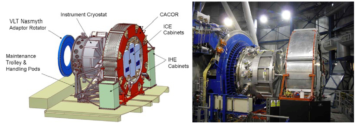
The opto-mechanical parts of the instrument are all contained within a single cryostat mounted on the instrument rotator at the Nasmyth focus of the VLT UT1 telescope. The total rotating mass is 2500kg of which 1100kg is the cold mass. At the temperature and pressure conditions on Paranal the optical bench was stabilized at a temperature of 115K. Because of the mass-limit on the instrument rotator (3000kg) the electronics cabinets are mounted on a separate instrument rotator (CACOR) sitting on the Nasmyth platform (see Fig. 1). The total mass during operations is 6000kg. KMOS was designed to have three identical modules, each of them comprising eight pickoff arm systems, eight IFUs, one spectrograph and one near-IR detector. This ensures that in case of failure of one system, 2/3 of the functionality will still remain. The following sections briefly describe the different sub-systems of KMOS in the order they are encountered along the optical path going from the telescope to the detector; further details can be found in [2]. 2.2Pickoff systemThe selection of targets is achieved by means of 24 cryogenic r-θ robots (‘pickoff arms’), which together patrol a 250mm (7.2 arcmin) field of view. This is located inside the cryostat below a vacuum-spaced doublet corrector which produces a flat telecentric focal plane. The pickoff arms are arranged into two different layers (“top” and “bottom”) of twelve arms each patrolling on either side of the focal plane, so that adjacent arms cannot interfere with each other. Each layer of twelve pickoff arms can patrol 100% of the field. The two motions (radius and angle) of the pickoff arms are both driven by stepper motors, which are modified for cryogenic operation. Whilst the positioning of the arms is open-loop via step-counting from datum switches, there are linear variable differential transformer (LVDT) encoders on each arm which are used to check for successful movement. In addition, a hardware collision-detection system is also implemented as a third level of protection which can sense when two arms have come into contact and then stop any further movement within a distance of <10μm. All 24 arms can be commanded to move simultaneously. A typical field re-configuration takes ~4 minutes and is accomplished whilst the telescope is slewing to the next field to avoid any additional dead time. 2.3Integral field units and filtersThe integral field units (IFUs) contain a set of fore-optics that collect the output beam from each of the 24 pickoff arms and reimage it with 2:1 anamorphic magnification on the image slicers. Immediately in front of the fore-optics is a filter wheel, which is used for order-sorting with the selected gratings. The IFU sub-system has no moving parts and uses gold-coated surfaces diamond-machined from rapidly solidified aluminium (RSA) components for optimum performance in the near-infrared and at cryogenic temperatures. The anamorphic magnification is required in order that the spatial sampling pixels (‘spaxels’) on the sky are square whilst maintaining Nyquist sampling of the spectral line profile on the detector in the spectral dimension. The 112 slices from a group of eight consecutive IFUs are aligned and reformatted into a single 254mm long slit at the entrance to one of the three identical spectrometers. All of the microoptics in the IFUs are produced using a combination of diamond-turning and raster fly-cutting techniques. Detailed metrology measurements were performed on every element to ensure that the stringent tolerances on form error and alignment for the IFUs had been achieved4. 2.4SpectrographsThe spectrograph sub-system is comprised of three identical units, which feed three detector sub-systems. Each spectrograph uses a single off-axis toroidal mirror to collimate the incoming light, which is then dispersed via a reflection grating and refocused using a 6-element transmitting camera. The five available gratings (IZ, YJ, H, K, H+K) are mounted on a 6-position wheel which allows optimized gratings to be used for the individual bands. A ‘blank’ position in the filter wheel is used for calibrations. 2.5DetectorsKMOS uses three Teledyne substrate-removed Hawaii 2RG HgCdTe detectors with 2048x2048 18μm pixels (one detector for each spectrograph). The detectors are operated at a temperature of 35K to minimize dark count and persistence5. Typical characteristics are QE>90%, readout noise <10e– rms for a single double-correlated sample (reducing to <3e– rms for long integrations with Fowler sampling), and dark current < 0.003 e–/sec/pixel). Each detector is adjusted manually for tip-tilt, but is mounted on a remotely operated focus stage which was used to set the optimum focus position during commissioning. Sample-up-the-ramp (non-destructive) readout is used as standard with Threshold Limited Integration (TLI) to extend the dynamical range for long exposure times. In this mode, if one pixel is illuminated by a bright source and reaches an absolute value above a certain threshold (close to detector saturation), only detector readouts before the threshold is reached are used to compute the slope and the counts written in the FITS image for this pixel are extrapolated to the full exposure time. This is an effective way to remove cosmic rays on these devices. 2.6Calibration unitFlatfield calibration (tungsten lamp) and wavelength calibration (argon and neon arc lamps) is carried out during daytime operations using an internal calibration unit located inside the cryostat. This provides a quasi-uniform light distribution simultaneously to all 24 fields when the arms are located at a calibration position at the edge of the field. Twilight flats are used for illumination correction (vignetting). 2.7Infrastructure and electronicsThe instrument housekeeping electronics7 (IHE) are mounted directly on the Nasmyth platform in two electronics cabinets, whilst the instrument control electronics8 (ICE) are mounted in three electronics cabinets which co-rotate with the instrument on the CACOR. 2.8SoftwareIn addition to the above hardware components, a customised data reduction pipeline has been provided for KMOS which allows the observer to evaluate the data quality after each readout using real-time reconstruction of the data cubes and apply sophisticated algorithms for co-adding of data cubes and subtraction of the sky background9. With over 4000 spectra per readout, automatic data processing and reduction methods have proved essential to exploit fully the scientific potential of KMOS. In addition to instrument control software and housekeeping diagnostics, KMOS has an optimised pickoff arm allocation tool, known as KARMA10, which links directly to the ESO observation preparation software (P2PP). KARMA assigns arms to targets in a prioritised way, whilst ensuring that no invalid arm positions are selected and allows the astronomer to manually reconfigure the list of allocated targets if required. 3.KMOS AIV & COMMISSIONINGFollowing a successful laboratory test campaign11, and a test readiness review by ESO, KMOS was shipped to Paranal in Aug 2012 to begin re-integration and installation at VLT UT1. The main cryostat and associated electronics were transferred via air freight, whilst the larger CACOR consignment was shipped as sea cargo. KMOS was fully re-assembled and re-calibrated in the new instrument integration hall at Paranal over an 8-week period in Sep-Nov 2012 by a dedicated team of technical experts from the consortium partners, working closely with ESO personnel. After an extensive set of verification tests, the instrument was taken up the final stretch of the mountain road at walking pace (Fig. 2), before being installed on the Nasmyth platform of UT1 (Antu). Because of the size of the CACOR (about four metres high), this item had to be lifted directly in through the dome aperture using an external crane (Fig. 2). Figure 2:KMOS cryostat on the road from the integration hall to the summit (left); the CACOR being hoisted into the dome of UT1 (right).  3.1First lightFirst light12 with KMOS at the ESO VLT occurred on 21st Nov 2012. Initially this involved pointing the telescope at a relatively bright star and taking short exposures with one arm at a time placed at the centre of the field. All 24 arms revealed a star image close to the centre of the IFU field of view (2.8x2.8 arcsec) much to the relief of the commissioning team. Even this relatively simple observation required a large number of systems to be working together such as the real-time display which showed the positions of the target objects in the pipeline reconstructed data cubes. The real-time display is a key feature of KMOS which allows the telescope pointing to be refined by placing a subset of the pickoff arms onto bright targets which are then centered automatically using a shift and rotation of the telescope field of view (in much the same way that bright reference stars are used to align the slit masks in a multi-slit spectrograph). Once the field is aligned, these acquisition arms can then be redeployed to fainter science targets if desired. 3.2Astrometric performanceOne of the first calibrations to be addressed was the astrometric positioning of the arms. This included both the mapping of the plate scale in the corrected focal plane(s) and also the local corrections (‘lookup tables’) which are used to take out the individual variations in the r-θ drives for each arm. The latter have to be defined over the whole pie-shaped region accessible to each arm, and were based on an astrometric calibration procedure using densely populated star fields in open or globular star clusters. Fig. 3 shows the absolute positioning accuracy of all the arms over the whole 7’.2 diameter field; 83% of the targets lie within ±1 spaxel (0.2 arcsec) of the centre of the IFU. The repeatability is <0.1 arcsec. Figure 3:Positioning accuracy of the KMOS pickoff arms measured using astrometric data for stars in the globular cluster Omega Centauri13. The red (solid) box bounds an area of ±1 spaxel, whilst the green (dashed) box shows ±2 spaxels. The IFUs cover a field of 14x14 spaxels.  3.3KMOS throughputA second key performance parameter is the system throughput. KMOS has a large number of optical surfaces in the optical train (18 air-glass and 15 reflective surfaces, excluding the grating and telescope mirrors) in order to deliver the performance capability of a multi-object integral field spectrograph. The throughput was measured on a number of nights using standard stars and is summarized in Fig. 4. The horizontal red (dashed) lines show the minimum requirements from the instrument technical specification2. Since the IZ-band and HK-bands were added later, on a best-efforts basis (with no impact on the design), there are no specific requirements for these modes. 3.4Spectral ResolutionThe spectral resolution of KMOS was determined using measurements taken from internal Ne and Ar arcs, and verified with observations of the unresolved OH emission-line spectrum in the YJ and H bands. The H-band results are presented in Fig. 5, which shows the FWHM versus column number (slit position) for the three detectors (spectrographs). Figure 5:Spectral line width as a function of slit position for four wavelengths within the H-band. The requirement of two pixels FWHM at the centre of the slit is shown by the dashed lines. The corresponding spectral resolutions listed in Table 1 comfortably exceed the technical specification. 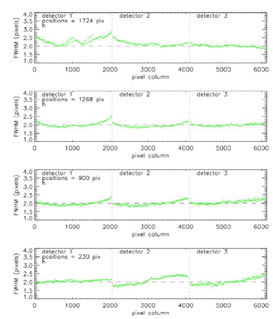 3.5Sky SubtractionOne of the key performance metrics of any multi-object integral field spectrograph is the ability to do accurate sky-subtraction, particularly in the infrared bands longer than 1 micron where the night sky spectrum is dominated by extremely bright and variable OH emission lines. With KMOS we have experimented with various sky-subtraction strategies including conventional offsets to blank sky with a fixed IFU pattern, and also using dedicated ‘sky’ IFUs to monitor the time-variability. Fig. 6 summarizes the performance of the different sky-subtraction modes incorporating the night-sky emission-line scaling laws from [14]. Tests using long exposures of faint emission-line galaxies indicate that residuals can be reduced to <1% except at the centres of the strongest lines, using a combination of these methods. Figure 6:An illustration of the quality of sky subtraction. On the left for a “simple” sky subtraction method, and on the right using an “optimal” sky subtraction method following the algorithm presented in [14]. The matrix shows arm-to-arm subtraction in the same exposure, e.g. the sky residual in IFUj using IFUk to estimate the sky spectrum. For comparison, the vector at the bottom shows the sky residual when the sky is estimated using the same IFU, but from a subsequent exposure, e.g. IFUj – IFUj in the classical A-B sequence.  4.KMOS SCIENCEFollowing three on-sky commissioning runs in Nov 2012, Jan 2013 and Mar 2013, KMOS was used for a set of science demonstration programmes proposed by the ESO community in Jun and Sep 2013. It was offered for community open time, and consortium guaranteed time, access from Oct 2013. Since then the instrument has been in heavy demand, leading to UT1 being the most oversubscribed (x6.7) telescope at Paranal in Period 92 (Oct 2013 – Mar 2014). KMOS has been used for a wide of scientific programmes ranging from exoplanet transit measurements through to searches for Lyman-α emission in extremely high redshift (z>10) galaxies. As an example we show in Fig. 7 the velocity fields measured for a sample of z~1 galaxies. Previous observations of such objects have relied on single-IFU observations, making the acquisition of representative complete samples prohibitively expensive in telescope time. Observations with KMOS have already more than doubled the number of such systems with good measurements of star formation rates and internal kinematics. Also in this figure we show a H-band mosaic of Jupiter obtained by stacking 16 dithered KMOS pointings with the arms in a fixed sparse grid pattern. This produces a unique wide-field infrared IFU capability with ~75,000 spectra covering a field of 65x43 arcsec at 0.2 arcsec spatial sampling. Figure 7:(left) Hα emission-line maps (top) and derived velocity fields (bottom) for a sample of faint z~1 emission-line galaxies in the GOOD-S field. The brightest targets have an observed integrated H-alpha flux of 1.0x10⁻¹⁶ ergs cm-2 s-1. These data were obtained with only 30mins of on-source exposure time during KMOS commissioning and demonstrate the power of this facility instrument for such surveys. (right) Reconstructed spectral image of Jupiter (pseudo colours refer to narrow bands extracted from the spectrum to highlight different molecular bands). This was created using the 24-arm mapping template with non-sidereal tracking and comprises nearly 75,000 spectra. The numbers refer to zones covered by specific IFUs during the dithered pointings.  5.5.REFERENCESSharples, R.,
“KMOS: an infrared multiple-object integral field spectrograph for the ESO VLT,”
in Proc. SPIE,
1179
(2004). Google Scholar
Sharples, R.,
“Design of the KMOS multi-object integral-field spectrograph,”
in Proc. SPIE,
44
(2006). Google Scholar
Rees, P.,
“KMOS pick-off arm optical alignment, calibration, and testing,”
in Proc. SPIE,
166
(2010). Google Scholar
Dubbeldam, M.,
“The KMOS Integral Field System: fabrication, alignment, and test of 1000+ optical surfaces,”
in Proc. SPIE,
84501M
(2012). Google Scholar
Masters, R.,
“KMOS: assembly, integration and testing of three 0.8-2.5 micron spectrographs,”
in Proc. SPIE,
168
(2010). Google Scholar
Finger, G.,
“Performance evaluation, readout modes, and calibration techniques of HgCdTe Hawaii-2RG mosaic arrays,”
in Proc. SPIE,
20
(2008). Google Scholar
Bezawada, N.,
“KMOS housekeeping electronics and its functions,”
in Proc. SPIE,
121
(2008). Google Scholar
Hess, A.,
“Implementation of the control electronics for KMOS instrument,”
in Proc. SPIE,
93
(2010). Google Scholar
Davies, R.,
“The Software Package for Astronomical Reductions with KMOS: SPARK,”
Astronomy & Astrophysics, 558 A56
(2013). https://doi.org/10.1051/0004-6361/201322282 Google Scholar
Wegner, M.,
“Achieving reusability in KMOS instrument software through design patterns,”
in Proc. SPIE,
28
(2010). Google Scholar
Sharples, R.,
“Status of the KMOS multi-object near-infrared integral field spectrograph,”
in Proc. SPIE,
84460K
(2012). Google Scholar
Sharples, R.,
“First Light for the KMOS Multi-Object Integral-Field Spectrometer,”
The Messenger, 151 21
(2013). Google Scholar
Bellini, A.,
“Ground-based CCD astrometry with wide field imagers. III. WFI@2.2m proper-motion catalog of the globular cluster ω Centauri,”
959
(2009). https://doi.org/10.1051/0004-6361:200810880 Google Scholar
Davies R.,
“A method to remove residual OH emission from near infrared spectra,”
1009
(2007). https://doi.org/10.1111/j.1365-2966.2006.11383.x Google Scholar
|