|
|
1.INTRODUCTIONImage sensors consist of devices that capture an image for purposes of display or storage. Current cell phones typically incorporate these image sensors, usually based on CMOS technology, which enables high quality images [1]. Cell phones are nowadays ubiquitous. Mobile phone CMOS image sensor market volume has grown 17% by 2013. The global mobile phone CMOS image sensor market volume is expected to reach around 2.44 billion units (estimated by 2013), and approximately 84.8% of mobile phones will have camera modules equipped. This is coming from the continuing penetration of dual-camera phones in the global market. Of the mobile phones and tablets in the market in 2012, most contained two camera modules. Focusing on the primary camera modules, the resolution trend we can have is a dominance of 5 Mpixels and 8 Mpixels sensors. A notable outlier is the 41 Mpixels image sensor. These facts allow the introduction of cell phones in the classroom as a unique tool for teaching and for simple technological training. In this paper we introduce some results obtained as a classroom experiment with image sensor cell phone and addressed to undergraduate students, 4th course of the Grade in Physical Sciences, at the Complutense University of Madrid. The subject: Optical Coherence and Laser is a specialized subject inside the specialization in Fundamental Physics. The objective of the work focuses on experimental methods for studying the basis of optical phenomena and that need to be extended to class room as a routine tool for students in physics and engineering. These methods can be simplified and easily implemented by the use of the new technical assistance provided by camera phones: classroom accessibility. In 2009, Z. Ben Lakhdar et al. introduced a procedure for studying diffraction and interference by the use of overhead projectors and camera phone image capture [2]. All these tools may be accessible in the classroom by the students. This technique can be extended to other optical phenomena, such as Holography. Here, we analyze and discuss the experimental results and feasibility to be offered as part of the practical lessons. The paper is organized as follows. In section 2 we introduce the basic concepts of holography and what it is a hologram. Section 3 is dedicated to the basis of diffraction and formation of the so called Fresnel zones to be applied for the diffraction of a laser beam by a circular aperture. Section 4 shows the experimental results using various camera phones. Section 5 is dedicated to conclusions. The paper ends with the references. 2.BASIC CONCEPTS OF HOLOGRAPHY AND IN-LINE HOLOGRAMHolography is nowadays a highly applied optical technique in many areas of optics and photonics, with applications in diverse areas of sciences such as beam conformation, laser technology and photonic devices, to name a few [3-5]. In 1948 Denis Gabor proposed a new microscopic method with the objective to improve the image quality and reproduction fidelity of images formed in a conventional microscope [6]. In 1971, Denis Gabor wrote in his Nobel Laureate Lecture [7] that holography is based on the wave nature of light. Indeed, the named Gabor hologram or in-line hologram is based upon the Fresnel diffraction originated by the free propagation of ideal punctual sources, generating the so called Fresnel zone. This diffracted beam is partially coherently superimposed with a reference beam then, forming the interference pattern that constitutes the hologram structure. The reading of the hologram with the reference beam reproduces the wavefront of the original point source. Figure 1 displays a simple scheme for the recording and reproducing of a Gabor hologram, with an ideal point source. We notice that any extended object can be considered as formed by a certain high number of point sources. Figure 1.-(a) Recording of the hologram of an ideal point source. (b) Reconstruction, two twin point source images are formed. See text for details  Figure (1a) corresponds to the recording process and Figure (1b) to the reconstruction one. In addition, and according to the basis for holographic recording, the recorded diffraction grating has a particular modulated structure in the thickness of the photomaterial (or in the detector). Then, for the case of coherent superposition of a plane wave (reference) and a cylindrical wave (object) the resulting structure corresponds to a parabolic grating [8]: Where t(x,y) denotes the transmittance amplitude of the hologram, ψo the object wave and iyψr the reference one. In all the following sections, we consider a linear behavior for the photomaterial or for the detector response function. The corresponding structure is represented as well in Figure (1b) in the hologram. We will observe that the diffraction pattern of the light beam projected onto the screen has a structure approximately analogous to the mentioned hologram constant phase surfaces distribution. Additionally, we have to concentrate in the theoretical foundations for Fresnel diffraction regime in order to formulate ψo. 3.FRESNEL DIFFRACTION BY A LIMITED APERTUREWe now have to study the basis of the diffraction of light by a fine limited aperture, with small dimensions compared to the wavelength of the incoming radiation (λ). The purpose is to establish the theoretical foundation for the interpretation of the recorded diffracted pattern in the mobile phone camera. The complex amplitude distribution of the diffracted light in an arbitrary plane in the propagation direction z>0 is: In eq. (2), ψp0(x,y) denotes the inverse Fourier transform of the incoming angular spectrum, G(x,y) is the propagator or Green function. The symbol * denotes convolution operation. For the Fresnel approximation we have to consider: i) z>>A. ii) Under paraxial approximations simplifies the mathematical representation for G that we will denote by h, the impulse response [9]: where A is the amplitude of the wave. Thus, the complex amplitude distribution of the diffracted field reads: For the particular case of a point source: If we consider now a finite circular aperture (associate to the limited aperture of the laser pointer) with radius r, the Fresnel integral can be expressed approximately as [10]: where: If we substitute eq. (7) in eq. (1) as the object wave and replace the reference wave by a plane wave: Aexp(ikz), we obtain: According to eq. (8) we observe that the holographic recording has the structure of a lens whose focal distance is parametrized by the spatial frequency of Fresnel Zone Plate (FZP) input. A numerical simulation of the structure of the FZP is displayed in Figure 2. Figure 2.-Structure of the recorded hologram whose transmittance amplitude is represented in ec. (8). This is the so named Fresnel Zone Plate (FZP) and gives the ideal structure as recorded by the camera phone.  The radius of the bright fringes: One observes that the radius of the FZP is proportional to the square root of even numbers. In the diffraction regime of the Fresnel Gabor hologram one has to reproduce the number of focal points produced by the lens provided that the hologram operates under thin hologram regime (i.e. Raman-Nath regime). Otherwise, if the hologram would operate under volume regime only the +1 and -1 diffraction orders would be reproduced. As a general physical interpretation, the FZP is a diffraction grating with focusing properties. It is both a positive and a negative lens, with f denoting the focal distance of the lens in eq. (9). In the current studied case we concentrate in analyzing the structure of the diffraction pattern as recorded by the mobile phone camera and will discuss how the phase of the Fast Fourier Transform (FFT) of the intensity distribution associated to the recording can exhibit some periodical structure as expected. 4.EXPERIMENTAL RESULTSThe main objective of the proposed classroom experiment is to teach undergraduate students in Physics the basic principles of Fresnel diffraction and holography. For this purpose, only very simple elements are required for the experimental procedure. Previously, the teacher must indicate to the students that they have to carry mobile phones for the classroom experiments. Usually, peer work is advised then the number of mobile phones and results to be compared can be reduced. Figure 3.-Operating in the classroom: A white screen is needed to project the laser beam source after propagating a certain distance. A simple tape meter can be used to fix the distance of propagation. Pictures are taken with the mobile phones. 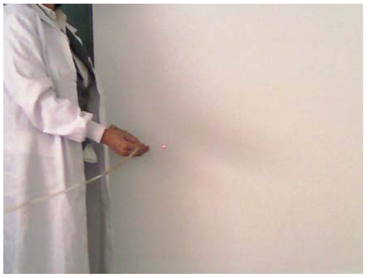 A laser beam coming from a laser pointer is projected onto the screen. The pattern has to be recorded as an image on the mobile phone. The distance of the laser beam propagation has to be fixed. For example, a distance of 3 m could avoid certain overexposure and that the image be saturated The students have to treat the recorded images by transferring it to a computer in the laboratory having a software for digital image treatment, intensity line profile determination and Fast Fourier Transform (FFT) operations. Figure 4 (a) displays the pattern recorded with a green laser pointer (λ = 532 nm, output power 3mW/cm2). We may notice that this particular type of laser operates under multimodal configuration as it was previously studied in a separate experiment [11]. However, the degree of spatial coherence is high enough as to obtain a good contrast of the captured image. Figure 4.-Pattern of the projected laser beam onto the white screen, captured by the mobile phone (NOKIA X3-02, see text for details), propagation distance 3m. (b) Line profile of the corresponding image. Abscissa horizontal line indicates the selected location for obtaining the line profile. Distance is measured in number of pixels.  Figure 4(b) shows the corresponding intensity line profile. Ordinate data corresponds to gray level. The software works with 8-bit images, comprising a total of 256 (i.e. 28) gray level. For data in Figure 4(b) it was used, in this particular study, a special program implemented in MathLab in our laboratory for obtaining of the line profile [12]. The line profile indicates the intensity distribution as a function of distance, measured in pixels. In the actual case, each pixel corresponded to 8 μm. The contrast can be estimated as well with a value of: C = 0.8. For the technical data of one of the used mobile phones, the camera of the NOKIA X3-02 has a sensor with 5 Mpixels and a digital zoom up to x4. The format of the recorded image is JPEG. As for other particular data, the laser pointer belongs to the class IIIa, and precautions have to be taken by avoiding any direct radiation to the eyes [13]. The image is first captured in a RGB format, comprising three superimposed images (i.e. channels) in red, blue and green, respectively [14]. In order to perform the Fast Fourier Transform (FFT), it has to be converted into a gray scale image, merging the three channels into a single intensity value for each pixel (Fig. 5-top). Then, the FFT algorithm is applied and the result for the intensity distribution is shown in Figure 5-Middle. We can observe a certain degree of saturation arising from the digital processing. The phase of the previously obtained FFT is displayed in Figure 5-Bottom. As expected, it recreates the intensity distribution with a quasi-circular geometry indicating the distribution associated to a Fresnel zone, as discussed in section 3. We have to consider that due to the particular experiment no further optimization has been performed and a certain distortion in the geometry is observed. A subsequent step, not considered here for brevity, will be the implementation of the digital image of the phase FFT in a computer in order to reproduce a digital hologram. We can advance that, in any case, the efficiency will be low. Obviously, the use of sophisticated high-resolution mobile phone cameras, will allow a high quality image and therefore, a higher quality hologram. Notice that the results displayed here were based on an image capture with a good quality phone camera. Nevertheless, the same process can be performed with diverse mobile phone cameras with different performance levels. As a key point, the students have to control not to record saturated images that will give diffraction patterns with a flat profile due to saturation to 256 gray level. A contrast level lower than 1 is required. Figure 5.-Top: Pretreated image of the laser beam as projected on the white screen. The RGB image is converted to a single intensity grayscale in order to perform the FFT. Middle: FFT of the laser beam projection. Bottom: Phase of the FFT (see Middle). Data: wavelength of the source: λ = 532 nm. Distance of propagation of the beam: 3m. Output power 3 mW/cm2.  5.CONCLUSIONSCamera phones are very useful for education and technical purposes. Over the last years, cell phones have become increasingly popular and are ubiquitous. Cell phones are now equipped with text messaging, internet, camera features, and other facilities. Cell phones offer many benefits for learning and are nowadays a very popular tool so called m-learning. Technologists can easily use them as a technical tool. The combination of laser sources with easy access to classroom, such as laser pointers, and cell phones provides a unique tool for the experimental demonstration of diffraction phenomena. In the current experiment students can observe the Fresnel diffraction phenomenon along with the concept of interference and holography. The additional digital treatment operation provides a very useful tool for other future applications. The great advantage is that it requires a very reduced infrastructure and can be implemented in the memory of cell phones. Combination with digital holographic techniques provides a quite promising tool for imaging data manipulation. 6.ACKNOWLEDGEMENTSThe author would like to express sincere thanks to Aitor V. Velasco, Alejandro Cámara and Elena Alonso-Redondo for very valuable help. Moreover, to all undergraduate students of the 4th Course of the Physics Grade, Faculty of Physical Sciences, Complutense University of Madrid. Partial financial support from the Spanish Ministry of Economy under Grant TEC2011-23629 is also acknowledged. REFERENCESBhatti, N., Baker H., Marguier, J., Berclaz J. and Süsstrunk,, S.,
“Cell phones as imaging sensors,”
in Proc. SPIE,
1
–19
(2010). Google Scholar
>Ben Lakhdar, Z., Dhaouadi, Z., Ghalila, H., Lahmar, L. and Majdi, Y.,
“Using mobile camera for a better exploitation and understanding of interference and diffraction experiments,”
in Proc. SPIE, Proceedings of the 2009 ETOP Conference,
(2009). Google Scholar
Rodrigo, J. A., Alieva, T., Cámara, A., Martínez-Matos, O., Cheben, P. and Calvo, M. L.,
“Characterization of holographically generated beams via phase retrieval based on Wigner distribution projections,”
Opt. Express, 19
(7), 6064
–6077
(2011). https://doi.org/10.1364/OE.19.006064 Google Scholar
Hernández-Garay, M. P., Martínez-Matos, O., Izquierdo, J.G., Calvo, M. L., Vaveliuk, P., Cheben, P. and Bañares, L.,
“Femtosecond spectral pulse shaping with holographic gratings recorded in photopolymerizable glasses,”
Opt. Express, 19 1516
–1527
(2011). https://doi.org/10.1364/OE.19.001516 Google Scholar
Velasco, A. V., Calvo M. L. and Cheben, P.,
“Photopolymerizable organically modified holographic glass with enhanced thickness for spectral filters,”
J. Appl. Phys., 113
(3), 033101-1
–5
(2013). https://doi.org/10.1063/1.4775787 Google Scholar
Gabor, D.,
“A New Microscopic Principle,”
Nature, 161
(4098), 777
–778
(1948). https://doi.org/10.1038/161777a0 Google Scholar
Gabor D., 1971 Nobel Laurate Lecture,
(2013) http://www.nobelprize.org/nobel prizes/physics/laureates/1971/gabor-lecture.pdf ( June ). 2013). Google Scholar
Solymar, L. and Cooke, D.J., Volume Holography and Volume Gratings, 17
–19 Academic PressLondon & New York,1981). Google Scholar
Goodman, J. W., Introduction to Fourier Optics, 66
–67 McGraw-Hill, New York
(1996). Google Scholar
Ghatak, A., Optics, 20.6
–20.7 Tata McGrawHill, New Delhi
(2012). Google Scholar
Paredes Barato, D. and Calvo, M.L.,
“On the Thompson-Wolf experiment. A study with laser sources,”
JEOS Rapid Publications, special issue 50th Anniversary of the Laser, 5 10051s
–7
(2010). Google Scholar
Alieva, T., Cámara, A., Rodrigo, J.A., Martínez-Matos, O. and Calvo, M.L.,
“Nuevas prácticas en óptica avanzada,”
New experiments in advanced optics] A Project for the Innovation and Improvement of Teaching Quality, Complutense University of Madrid,
(2011). Google Scholar
Cámara, A.,
“Advanced Practical Experiments in Optics,”
(2013) http://pendientedemigracion.ucm.es/info/giboucm/index.php?option=com content&view=article&id=36&Itemid=48 Google Scholar
|