|
|
1.INTRODUCTIONOptics is a core component of an undergraduate physics degree. Not only is optics a fascinating topic on its own, but a good understanding of optics helps students gain valuable insight into more complex topics. A working knowledge of optics is vital for the experimental investigation of astronomy, quantum mechanics, and a host of other research endeavors involving optical measurements. Research is also a critical part of a student’s education. Participation in research brings tremendous benefits to a student. So what do the students gain by participation in research? They learn independence. They learn how to plan a project. They learn the process of discovery. They learn that all answers are not always found on the internet, from professors, in books and publications (in that order). Research makes the “book” learning real. But what skills do the students need to be able to do research? Most of our experimental research opportunities involve optics. We have students working on investigations that range from atomic spectroscopy of rubidium to Rayleigh scattering to optical tweezers to quantum optics. When a student starts research, we want them to be ready to go. We don’t want them to have to relearn material (or for us to reteach material) that they should already have mastered in earlier classes. One question that is arising more frequently at present with the advent of the Massive Open Online Course (MOOC) and on-line courses is the push for virtual labs. This forces us to consider what is the value of the instructional laboratory segment of the course? What goals are we trying to achieve in this laboratory? In this report we will, hopefully, show that there is significant value in the laboratory with the caveat that the pedagogy of the laboratory is vitally important. In our program there are a number of laboratory course (see the sequence shown in Figure 1). Of importance to this report is the sequence of labs: Introductory 1, Optics Lab, followed by Advanced Lab. Students are required to take “advanced laboratory” after having completed Intermediate Optics and Optics Laboratory. Advanced Laboratory, to date, has been the capstone laboratory experience for our students. In Advanced Lab the students are required to work semi-autonomously on several projects during the semester and write quasi-professional publications which are peer reviewed by students at another university through an on-line journal: Journal of the Advanced Undergraduate Physics Laboratory Investigation (JAUPLI)1. Many of the investigations the students perform are optics based. These investigations include such topics as building an optical tweezer system, assembling a system to study Brownian motion, Raman spectroscopy, real-time holography, Schlieren imaging, or interferometry. These are not canned investigations. Rather they are investigations in which the students must have significant skills in assembling optical systems. It is through observation of student behavior in the Advanced Laboratory and in research that we discovered significant flaws in our optics course and laboratory. This has led to our gaining insight into the value of labs and better laboratory pedagogy. Our observations of student work in both research and the “advanced laboratory” indicated that the students were ill prepared for doing independent work. They made use of haphazard optical set ups often involving stacked books and even, on one occasion an empty Coke bottle that the student insisted was a critical optical component. The students used trial and error for setting up optical systems without consideration of light capture capabilities. The lecture part of the optics course seemed to have had no impact on what students did in the lab. It is unclear whether students saw no connection between lecture work and experimental work or that they felt it would be faster to just play with the equipment as opposed to thinking about the problem. What we see all too often is students resorting to a random systematic measurements (RSM). That is, a student randomly selects one parameter and then systematically varies it in the hopes that their persistence will eventually lead to success. Why was this case? 2.PRE 2006Let’s first consider only the optics component of a physics student’s education. Traditionally, a student in an introductory physics class might be exposed to optics for only a small fraction of the second semester introductory physics class. In the associated laboratory a student would see, at most, five weeks of optics related laboratories. They would experience nominal investigations in geometric optics, single and double slits, diffraction gratings and spectroscopy; a new topic per lab session. These laboratories would be extremely prescriptive – essentially guided demonstrations - which required little student thought, creativity, or investment. The situation in lecture is worse. Our second semester introductory physics lecture must cover thermal physics, electro- and magneto- statics, waves, as well as geometric optics, and physical optics. Under the most auspicious of circumstances there may be three weeks devoted to geometric and physical optics. Clearly the students can only leave this laboratory and class situation with a rudimentary understanding of the most basic of optics and devoid of hands on experience. The Intermediate Optics class and Optics Laboratory did little to improve student understanding. The class would endeavor to build upon the weak foundation developed in the introductory course and proceed to give the students a highly mathematical representation of optics through lecture. A method in which the students copy what is written on the board into their notebooks. This approach of heavily mathematical lectures is a problem for the students because they are still novices in physically interpreting mathematics. Because the laboratory was simply a series of guided demonstrations, it added little value to student learning. Additionally, the optical equipment was marginal at best. It was not surprising that the students struggled with optics when asked to function independently. 3.THE REMEDY – AN OVERVIEW OF LABORATORY AND LECTURE REVISIONSThis was a situation in dire need of a remedy. We performed a complete revision of the pedagogy in the Intermediate Optics and Optics Laboratory. The class and laboratory were altered from straight lecture to using interactive engagement.2-5 In brief, interactive engagement is a process by which the students are posed questions and led to answers rather than being simply told how to do something. There is debate and discussion about the topics and instructor posed questions. The instructor guides the student discussion. This process builds a sense of ownership of the knowledge developed through class in the students. Interactive engagement has been applied predominantly in introductory courses. Most recently, there have been a number of attempts to apply these techniques to intermediate and advanced classes.6-9 Our implementation of this method involved a significant use of tutorials to help the students gain physical insight and mathematical sophistication. The laboratories were designed so that each laboratory would build on the previous so that students cannot simply follow a “memorize and dump” strategy in which each lab activity is completely independent and irrelevant to subsequent labs. Activities were developed so that students were forced to predict expected outcomes, and then test whether their predictions were correct. Whether their results agreed with the prediction or not, the students had to reflect upon, and articulate the meaning of what they had observed. However, there are drawbacks to this format of laboratory and class: to be successful the students must have time to think. This makes both lecture and laboratory move more slowly than a mere “telling” the students in class and simply having them follow directions in laboratory. 4.DESCRIPTION OF LABORATORIESThe laboratory sequence that we developed was focused on geometric optics and polarization. We chose to leave interferometry out of the intermediate optics laboratory because we felt that with limited time, we could only develop superficial student understanding of interferometry and the labs would devolve into instruction based laboratories rather than the predict and reconcile observations used in all of the other laboratory activities. The sequence of topics is shown in Table 1. One example activity is based on the student pre-concept that all rays pass through the focal point when forming an image. The ramifications of such a belief are that a clear image can be formed at multiple locations and that this image gets larger as you move farther away (see Figure 2a). To help students gain greater insight, it is necessary that they actually experiment by limiting the number of rays to those passing through the focal point by use of a small aperture placed at the focal point. Students are asked to predict what will happen if the aperture is placed at the focal point and then test this experimentally. They also must examine image location as they move the screen back and forth noticing that the small range of image distances (see Figure 2b). Figure 2b –investigation that forces students to confront their prediction with experimental evidence  Table 1
The critical part of each of the investigations in this laboratory sequence is that the students must commit to an answer, then make observations and reconcile these observations with their previous prediction; articulating the meaning of their observations. Another very important aspect of these labs is that students must provide evidence beyond simply saying they saw something. They must take photographs and interpret these photographs. The lecture also concentrated on fewer topics. These topics are also shown in Table 1. All materials for labs and lecture tutorials are available on the web at http://users.ipfw.edu/masters/Optics_CCLI_Project/optics_ccli_project.htm. 5.ASSESSMENTAs with any experimental investigation, it is critical that we determine the results of the investigation. Certainly in any experiment, we would collect, examine and analyze the data. In curricular changes we must do the same. The question is: what data do we have? The first set of data is direct observation of student behavior. Do the students continue to use unstable optical set ups after Intermediate Optics? Do they continue to use trial and error in optical system design? We can make these observations in the Optics Laboratory, the Advanced Laboratory and the research laboratory. The two trials (2008 and 2010) immediately following the change in course and laboratory structure indicated a change in student behavior as observed either in student research activity or in Advanced Laboratory. For the 2008 trial, 60% of the students were deemed very competent based on their skill in designing and the care in assembling optical systems. Another 10% were considered competent. This lower ranking was predominantly based on struggles the students had in designing optical systems. The remaining 30% were considered novices. For the 2010 trial, 30% of the students were deemed very competent and another 20% were considered competent. The remaining 50% remained novices. From the Optics Laboratory activities, we examined student answers and explanations on all of the lab activities. Using a rubric we rated the quality of the student answer and also the quality of explanation. The scale was 0-blank, 1 – poor, 2 – improving, and 3 – good. Table 2 shows a sampling of the data. What was of most concern to us was the quality of explanations seemed to decrease in the 2010 trial in some very key points. Table 2
Why did this decrease take place? Was there a correlation between our judgment of optics competence based on observations and this decrease in quality of explanation? Our deliberations into this matter led us to consider the 2010 cohort’s other laboratory experiences. In every other laboratory (post introductory), these same students (from the 2010 trial) had struggled. The only difference that we could identify in the education of these students was the pedagogy used in the introductory lecture and laboratory. The lectures were very traditional and non-interactive. The laboratories were “cookbook;" recipes to be followed to get an answer without much thought. Every laboratory was independent. Our conclusion was that this introductory laboratory (and perhaps class) had a significant impact on these students expectations of laboratory. How the introductory laboratory was taught set the tone for how the students performed in all subsequent labs. Changing the student expectations becomes more difficult every year. 6.THE OPTICS CONCEPT ASSESSMENT (OCA)The third data source indicating impact of the course and laboratory change is based on a conceptual test, Optics Concept Assessment (OCA), we developed administered in the students in the 2010 trial. This test is attached in Appendix 1. Table 3 shows some near universal pre-instruction concepts. Some of these concepts (labeled persistent) have been very difficult to remove. Table 3– This table lists all of the significant pre-concepts we have seen
In Intermediate Optics we have two groups of students. One group is the physics majors. These students take the laboratory. The other group is the engineering majors. These do not take the laboratory. Table 4 shows the results of pre-post tests using the OCA for these two groups. Table 4.
It is significant that the students who took the laboratory showed improved more on the OCA than those who did not. Laboratory makes a difference! 7.IMPLICATIONS FOR INTRODUCTORY LABORATORIES (AND “LECTURES” TOO)While it is always difficult to make comparisons from one class to another, especially with the small numbers of students involved in our intermediate optics class and laboratory, we believe that the differences between the 2008 and 2010 trials were significant enough that they imply some important results. The main difference we see between these two groups is the pedagogy of their introductory laboratory. If a laboratory is taught in such a way that it does not instill inquiry in the students, then the students struggle with the inquiry based format in later, more advanced laboratories. Science is based upon inquiry and this is a critical aspect to the laboratory experience that should not be neglected. This is evidence that the format and pedagogy of the laboratory is critical. However we have evidence that lecture and laboratory are a coupled educational experience. We have observed that students in an active learning, inquiry based laboratory coupled with a traditional lecture struggle in the laboratory. The students struggle much more than students who are in an inquiry based laboratory with an inquiry based “lecture”. These observations have led us to conclude that the pedagogy of a class impacts how students learn in the laboratory. Given these observations, we have since modified how our introductory labs are taught. All laboratories in our department are now inquiry based. This, however, lead us to question our first semester introductory physics laboratories. These laboratories typically cover the same materials covered in the class focusing on motion and forces. However, this overlap between class and laboratory seemed to be an inefficient use of educational time. So we took the set of laboratories that were originally used in Optics Laboratory, and used them in the first semester introductory physics laboratory. This gave students approximately 24 hours of hands-on optics experience through the entire semester. There was no class time spent on optics. All student learning about optics was through the laboratory. Using the OCA as a measure of student learning of optics material, we see a reasonable improvement in student understanding of geometric optics entirely through the laboratory experience. We also checked to see if removing the laboratory experience in motion and forces harmed the student through use of the Force Concept Inventory test. There did not appear to cause a significant decrease in student learning of mechanics concepts taught only through interactive “lecture”. Some of these students also took Intermediate Optics class and Optics Laboratory the following year. These results will be described in next section. 8.MEANING OF LABORATORY?As we continued with these predict and reconcile laboratories, we began to feel that there were several critical ingredients missing from the laboratory. Those ingredients were the “oh wow” factor and the process of “discovery.” The laboratories to date had been solid pedagogically and they improved student understanding. But they were also a little boring. The question was how to add the process of student discovery AND have them actually observe and be astonished by both their own discoveries and explanations. This seemingly simple desire has been exceedingly difficult to achieve. To date, we have had any notable success. There was another aspect of the labs that was troubling. Communication is critical to student synthesis of the information in the laboratory. But the labs were configured to be completed by students writing “short answers” of approximately a paragraph in length. These answers are discrete and because there was no requirement for them to put the ideas together into a full “story,” it was very possible for a student to have internal contradictions. Starting in 2011 and continuing into 2012, the students were required to write papers for each laboratory activity completed. These papers were not simply “lab reports.” Rather they are intended to be synthesis building activities. This is difficult to accomplish because the students tend to write for the instructor rather than for themselves. In the subsequent two trials (2011 and 2012) we attempted several modifications. The sequence of topics used were essentially the same as those (see Table 5 for a list of the labs performed). However, we modified the labs by removing some of the directives and making the labs more open ended. The lab write-ups became outlines of what the students had to figure out. Some rose to this challenge and developed very interesting techniques to perform specific measurements. Others struggled. Table 5– notice that this laboratory sequence is essentially unchanged from the earlier ones. Simply the laboratory directions were changed.
In 2012, the laboratory sequence of 2011 was refined. The detailed directives of “set this up”, “look at that” were stripped from the laboratory and the students were instructed to predict what would happen under certain circumstances then test their prediction, or told they needed to accomplish some task. For example, the students were given a half waveplate and told that they needed to figure out what it did. They were given a quarter waveplate and had to determine its impact on polarization. The latter was very challenging. They had to use a motorized polarization analyzer that they assembled and they had to then pay very careful attention to the “floor” and “ceiling” of the sinusoidal signal they recorded as the analyzer rotated. They then had to determine what that meant! The lab sequence is also shown in Table 5. Notice, the topics covered have not changed significantly. One problem is that while the previous labs were too long, the 2012 labs became even longer and resulted in students spending up to six hours beyond the three hour laboratory time, every week. Students were expected to write The 2012 intermediate optics class and laboratory was also the first to have students who had previously had an optics sequence in their first semester introductory laboratory. So it might be expected that they would be more advanced. This was not the case. One of the chief differences is that the students go from an optical rail setup to an optics laboratory (see Figure 3). With the optical rail, the students have only one degree of freedom. Everything is rigid. But in the optics laboratory, there are many degrees of freedom, all three dimensions, angle of optics, etc. Additionally, in the introductory laboratory, there is an extremely limited set optical elements while in intermediate optics, the variability is tremendous. Figure 3 –Comparison of introductory physics optical equipment with Optics Laboratory equipment showing the greater number of degrees of freedom in the latter. 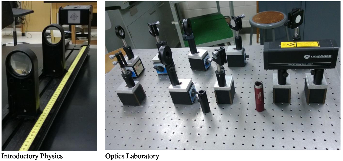 Student performance in the advanced laboratory and in research has been somewhat disappointing. For example, in advanced laboratory, one student struggled to set up simple imaging using a pair of mirrors for Schlieren imaging, while another seemed to complete the activity with few difficulties. Another student clearly had difficulty understanding imaging for Raman spectroscopy, but several others were able to assemble microscopes for optical tweezers and studying Brownian motion. One student spent inordinate amounts of time attempting to image the entrance slit of a spectrometer without the use of a lens. Overall, the results are muted; not as good or at least no better than in the previous labs. From the 2011 trial, approximately 30% of the students were deemed very competent, another 30% were considered competent and the remainder continued to behave as optics neophytes. We have not yet collected complete data on the 2012 cohort since not all of the students have had a chance to take Advanced Laboratory. However, of those that have taken Advanced Laboratory, only 30% could be deemed competent. All the trials are compared in Table 6. Table 6
The OCA results for these two trials are shown in Table 7. We use them purely to measure improvement in understanding. However, it is interesting to note that the 2012 pre-test results indicate a strong success of the change in introductory laboratory pedagogy. Every student in the 2012 cohort had had an inquiry based laboratory. Some of them had had an optics based introductory laboratory 18 months previously. Yet these same students scored 30% higher on the pretest than those that had not had inquiry based introductory laboratories (all previous years)! Table 7
Unfortunately, this same data tells us that between Intermediate Optics Lecture (which discarded the tutorial system in 2011) and Optics Laboratory (which removed structure in 2011) we seem to have hit a ceiling. We cannot add greater value to the students’ optics education even though they are coming in better prepared. This provides a new challenge! 9.CONCLUSIONSWe have developed a sequence of laboratories and tutorials which, when used together seem to work well to help students learn basic optics. The evidence we have collected indicates that laboratory can be extremely useful for student learning of optics. This data also indicates the importance of inquiry based learning in both lecture and laboratory. It indicates the importance of the introductory laboratory to set the tone for all future laboratory courses. In this era of Massive Open Online Courses, this information is critical. The laboratories that can be provided either by virtual laboratories or through at home kits are not the same as those that can be provided with faculty guidance. And since these laboratories set the tone for later, more advanced laboratories, removal of these introductory laboratories would greatly damage the subsequent laboratory experiences which build upon the inquiry skills developed early on and ultimately the ability of a student to participate in real research. As we forward with development of these laboratories, we will have to have a redesign process. We have, for the moment, terminated the optics in introductory physics investigation. It was difficult to keep the lab instructors as focused as necessary for that method to succeed and as it was originally engendered it was extremely instructor time intensive because of writing requirements. We may reconfigure these introductory laboratories with a easier to assess method. We are also going to investigate how we can keep the positive qualities of the previously developed labs while giving the students the chance to discover the physics. Discovery is very difficult because you have to have a lot of background knowledge and a significant skill set that is just being developed through the educational laboratories. Finally, we will most certainly include writing and oral communication requirements in all subsequent revisions. ReferencesDavid E. Meltzer and Ronald K. Thornton,
“Resource Letter ALIP--1: Active-Learning Instruction in Physics,”
Am. J. Phys., 80 478
(2012). https://doi.org/10.1119/1.3678299 Google Scholar
Richard Hake,
“Helping Students to Think Like Scientists in Socratic Dialogue-Inducing Labs,”
Phys. Teach., 50 348
(2012). https://doi.org/10.1119/1.3670087 Google Scholar
““Don’t Lecture Me”,”
Patricia Blanton, Phys. Teach., 49 523
(2011). https://doi.org/10.1119/1.3651744 Google Scholar
Louis E. Keiner and Teresa E. Burns,
“Interactive Engagement: How Much Is Enough?,”
Phys. Teach., 48 108
(2010). https://doi.org/10.1119/1.3293658 Google Scholar
Mark F. Masters and Timothy T. Grove,
“Active learning in intermediate optics through concept building laboratories,”
Am. J. Phys., 78 485
(2010). https://doi.org/10.1119/1.3381077 Google Scholar
Christopher M. Sorensen, Dyan L. McBride, and N. Sanjay Rebello,
“Studio optics: Adapting interactive engagement pedagogy to upper-division physics,”
Am. J. Phys., 79 320
(2011). https://doi.org/10.1119/1.3535580 Google Scholar
Stephanie V. Chasteen, Steven J. Pollock, Rachel E. Pepper, and Katherine K. Perkins,
“Thinking like a physicist: A multi-semester case study of junior-level electricity and magnetism,”
Am. J. Phys., 80 923
(2012). https://doi.org/10.1119/1.4732528 Google Scholar
Benjamin M. Zwickl, Noah Finkelstein, and H. J. Lewandowski,
“The process of transforming an advanced lab course: Goals, curriculum, and assessments,”
Am. J. Phys., 81 63
(2013). https://doi.org/10.1119/1.4768890 Google Scholar
AppendicesAPPENDIXPlease note that an answer key is available by request. Send requests to grovet@ipfw.edu Optics Concept Assessment 3.7
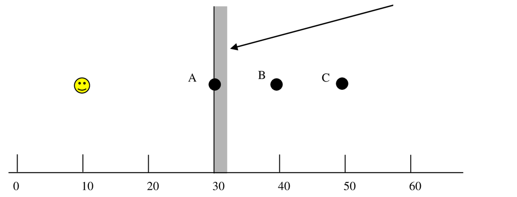
Consider the following sketch for the next two questions. A laser beam passes through two closely spaced circular holes and then to a distant screen as shown below (more distant than 1000 times the separation between the small holes). NOTE: A is directly opposite the upper hole, C is directly opposite the lower hole, and B is halfway between points A and C.
For the next two questions consider the sketch shown below. Two equivalent flashlights shine light through a red glass plate to a pair of see-through screens. The light from the Flashlight 2 must travel a longer distance to its screen. As a result, screen 2 is larger than screen 1.
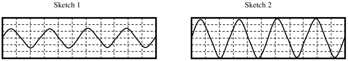
For the next three questions suppose we can take a photograph of light that shows how the light wave crests/troughs (shown as vertical differences) change with position (shown horizontally). Sketch 1 represents green light. In the second sketch (sketch 2), the light was changed such that the wave crests are double in size and the troughs are twice as deep (all other light parameters that are not necessarily changed remain the same).
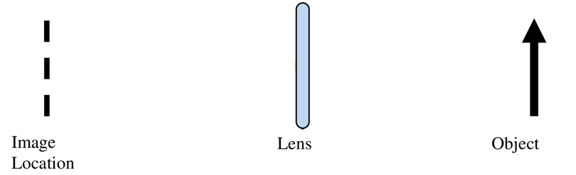
Use the following sketch to answer the next two questions. A single lens is used to form an image on the side of the lens opposite that of the object. The image is not drawn, but its location is indicated by the dashed line.
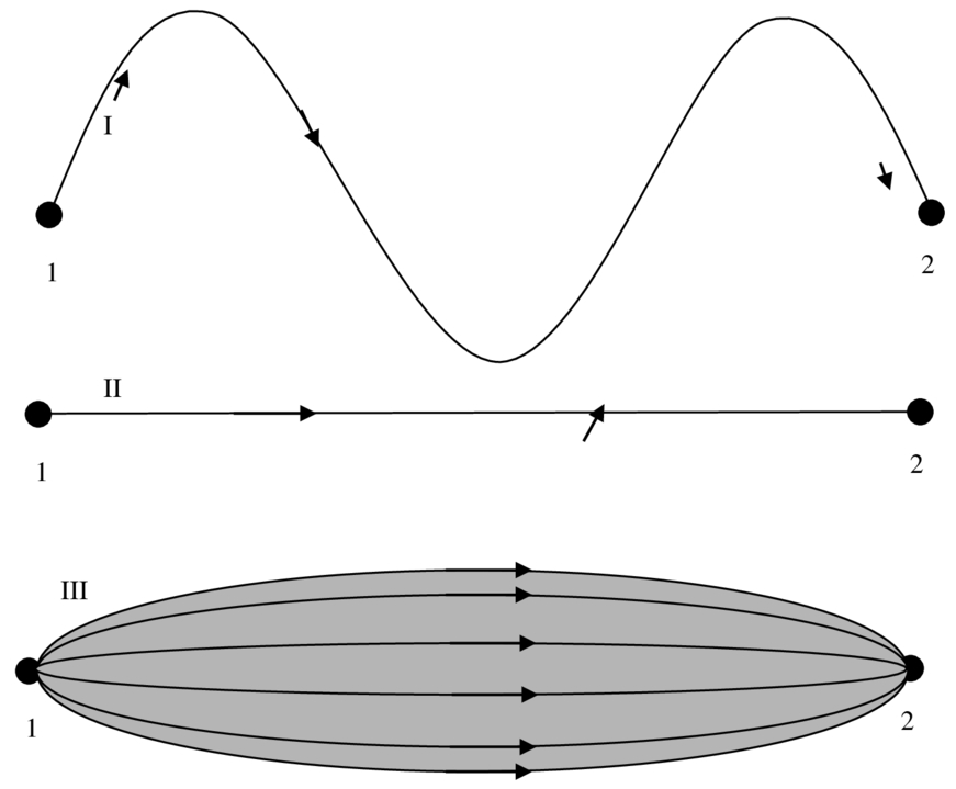
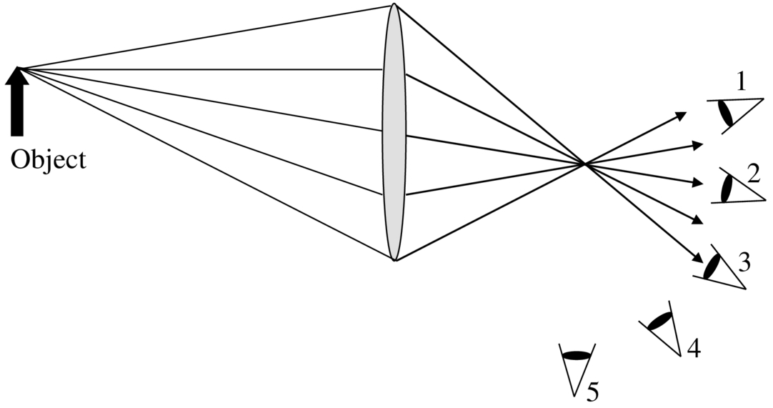
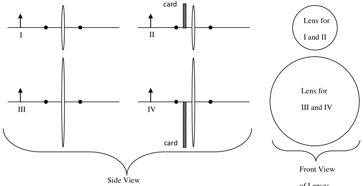
For the next 4 questions consider the four diagrams shown on the next page. Each diagram shows a converging lens. The lenses are drawn in the sketches as ovals (because the sketch is looking at the lens on their edges), but if a person looked directly into the lenses, their outer perimeters would be circular. An arrow-shaped illuminated object (marked by an arrow pointing up) is placed the same distance to the left of each lens and in each case has the same brightness. The two small circles on either side of the lenses are one focal length away from the lens. Diagrams II and IV have business cards that cover half of the lens. For all four cases, the object is the same distance from the lens and all the lenses have the same focal length. The image is not shown for any of the four diagrams. This does not necessarily mean that there is no image or that an image is present.
|