

|
|
1.INTRODUCTIONNow that curved grazing-incidence mirrors have become a standard component for focusing X-ray beams at synchrotron beamlines, the development of active mirrors, whose surface figures can be varied according to the user’s needs, has become a subject of intense research. In many cases, a highly polished silicon crystal or silica substrate has been provided with a controllable bender on each end to make it into a deformable X-ray mirror. A more versatile type of mirror, the bimorph, has been developed more recently.1–3 Here the polished silicon or silica substrate is mounted on a pair of piezoelectric plates of opposite electric polarization. Electrodes allow the correction of figure errors of wavelengths longer than twice the electrode interval. Early difficulties with bimorph mirrors, particularly the “junction effect,” the appearance at plate junctions of surface kinks that broaden and break up the focused beam, have been solved by re-polishing the surfaces.4, 5 After re-polishing, no further deterioration was observed. Recently, in response to users’ demands, interest has moved from the simpler problem of beam focusing to the more general problem of beam shaping, which is already a conventional technique for laser beams. The generation of a “tophat” beam, a beam of uniform intensity across a specified width, is a textbook problem in laser physics and is greatly desired by X-ray synchrotron users because it reduces the rate of radiation damage in fragile samples and relaxes the tolerance for errors in the position of small samples. Spiga et al6 developed a model for calculating optimal mirror figures for transforming a specified intensity distribution on the mirror into a different specified intensity distribution at the sample. Inevitably, however, polishing errors with wavelengths of millimeters remain even after the junction effect is removed. Experimental data presented in this article confirm that figure errors of this scale introduced by polishing give rise to striations in the beam, causing hot spots at which a sample would suffer more rapid radiation damage. It will be shown that the reflected beam can be strongly striated even when the mirror’s slope errors are reduced to nearly state-of-the-art levels of 0.5 µrad, thus proving that figure errors that are acceptable for focusing do not necessarily yield acceptably uniform defocused beam. Theoretical calculations also based on geometrical optics7 indicate that the relationship between the mirror’s slope errors and the reflected beam striations is nonlinear, which complicates attempts to mitigate the beam structure. Through calculations, simulations and experimental data, the relationship between surface figure errors and beam striations will be investigated. 2.EXPERIMENTAL TRIALS2.1Validation of geometrical opticsThe previous papers of Spiga et al6 and of Nicolas and Garcia7 base their predictions of beam structure on geometrical optics, and a series of measurements collected from the vertical focusing mirror of Diamond’s beamline I02 confirms that geometrical optics is a suitable model for practical cases. This mirror is a re-polished THALES-SESO bimorph of 600 mm length with 8 electrodes. It is located 33.115 m from the undulator source and focuses the beam onto the sample 6.885 m downstream. The grazing incidence angle at the center of the mirror is 2.7 mrad. Upstream from the mirror was a double crystal monochromator that selected X-rays of energy 12.658 keV. In situ pencil-beam scans were taken to determine the local slope errors of the mirror as shown in Sutter, Alcock & Sawhney.4 The pencil-beam scans were used to determine the piezo response functions, which show how the figure of the mirror changes with a given voltage increment to each electrode. Using the piezo response functions, the voltages required to shape the mirror for focusing on the sample were calculated by the method of Hignette, Freund & Chinchio.8 The same response functions were then also used to determine the voltages that would add a uniform curvature along the entire length of the mirror in order to broaden the beam at the sample to a specified width. At each selected beam size, another pencil-beam scan was taken in order to measure the slope profile of the mirror’s surface. A simple model based on geometrical optics was developed in order to generate a theoretical profile of the reflected beam’s intensity at the sample. The principle is illustrated in Fig. 1. At each position of the incident beam slit in the pencil-beam scan, the measured slope error of the mirror determines the position of the reflected ray on the detector, which in this case is a scintillator whose image is focused onto a CCD camera. A Gaussian peak, whose width is equal to the slit width (10 µm) and whose area is equal to the measured area of the beam in the camera, was then assigned to this position. The sum of all Gaussians over the pencil-beam scan produces the theoretical beam profile at the detector. Note that interpolation, which requires assumptions about the slope errors between the measured points, is unnecessary. Figure 1.Schematic of ray-based model for determining the profile of reflected beam on the detector from the local slope errors of a mirror.  The theoretical beam profiles at the sample position were then compared with measured knife-edge scans. Fig. 2 shows the pencil-beam scans, beam images, and the theoretical and measured sample beam profiles for three different final beam sizes. Geometrical optics clearly explains how the structure of the beam measured at the sample position by the knife-edge scans arises from the mirror slope errors measured by the pencil-beam scans. Note, however, that the rms slope error on the mirror is only 0.5 µrad, yet produces very strong striations. More accurate calculations of the profile could include the proportionality of the width of each Gaussian to the local curvature error at the section of the mirror that produced it. This was discovered in pencil-beam scans of one of Diamond’s mechanically bent mirrors. However, it would not change the conclusions of this section. 2.2Demonstration of large beam structure from small slope errorsTests of striations in defocused beams produced by a bimorph mirror with a surface highly polished by elastic emission machining (EEM)9 place an even more stringent upper limit on the tolerable slope errors. Thales-SESO manufactured and assembled the bimorph layers, then JTEC Corporation (Osaka, Japan) polished the reflecting silica substrate deterministically, and finally Thales-SESO attached the electrodes. The mirror assembly is 150 mm long and has 8 electrodes. It was examined at the Diamond optics test beamline B16, where it was placed 46.5 m from the bending magnet source at a grazing incidence angle of 3 mrad. Detectors were placed 0.4 m downstream from the center of the mirror because the mirror was pre-shaped to focus at this distance. The mirror was illuminated with 8 keV X-rays selected by a double crystal monochromator. Because the mirror’s short focal distance and the bending magnet’s relatively low X-ray flux made it difficult for pencil-beam scans to obtain slope error data with sufficient precision, the speckle-based method of Berujon et al10, 11 was used instead to measure the wavefront errors at the detector and to generate the piezo response functions. An additional simple uniform curvature was first added to the mirror’s surface profile in order to broaden the beam to a 60 µm width at the detector position. The measured wavefront was fit to a sphere, and the slope errors were calculated from the fit’s residual. After optimization of the electrode voltages, the slope error of the EEM bimorph was minimized to 0.15 µrad as shown in Fig. 3. Figure 3.Plot showing minimized slope error of EEM bimorph according to speckle-based technique. The rms slope error along the length of the mirror is 0.146 µrad. The best-fit radius of the wavefront was 3221.77±6.90 mm.  Once the voltages of the EEM bimorph’s electrodes had been set to obtain a beam of 60 µm width at the mirror’s nominal focal distance, and the remaining slope errors on the mirror’s surface had been minimized, the beam profile was measured with a camera and then with a knife-edge scan. The results are displayed in Fig. 4. Notice that striations that are not visible in the camera image are clearly visible in the knife-edge scan. Thus, even a slope error of only 0.15 µrad rms can leave clear structure in the defocused beam profiles. Figure 4.(Left) Camera image (0.45 µm/pixel) after optimization of voltages using the speckle-based method to obtain 60 µm wide beam at detector position 0.4 m downstream from center of mirror. (Right) Intensity profile of beam at 0.4 m downstream from mirror after optimization to lowest mirror slope error. This was determined by differentiating the knife-edge scan, then applying a 3-point smoothing algorithm to the derivative to remove numerical noise.  3.MITIGATION OF BEAM STRUCTURENicolas and García7 have shown that the intensity modulation within a defocused beam depends nonlinearly on the slope profile of the mirror. Therefore it is not easy to predict whether a given surface error introduces acceptable or intolerable striations in a defocused beam. However, there is a very simple, mathematically tractable model that can still be justified by experiment. First, for a mirror that is sufficiently short compared to its focal length, Fig. 2 shows that the ideal slope profile for introducing a defocus is approximately a straight line. Then, Fig. 5 shows that the imprint remaining on the EEM bimorph mirror after voltage optimization is an oscillation whose period matches the spacing of the electrodes. A theoretical model of the electrodes’ response functions, which will be introduced in §4, also yields an oscillating imprint. Now, let x be the coordinate along the length L of a mirror.x = 0 will denote the center of the mirror, and positive x will be toward the image. Therefore −L/2 ≤ x ≤ +L/2. The figure of the mirror will be given by a function y(x): Figure 5.Figure error measurements of the EEM bimorph made on the Diamond-NOM optical deflectometer13 after voltage optimization. The remaining rms figure error of 0.87 nm is the imprint left by the eight discrete electrodes. 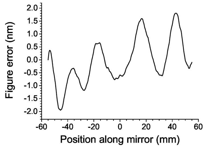 P(x) is an ideal pre-ground shape of the mirror. Usually this will be a simple geometrical function such as a cylinder, ellipse or parabola. A(x) is a purposely induced change in the mirror’s figure from the simple function P(x). This change may be introduced by using the mirror’s actuators. For example, if the mirror is a rectangular slab with a 4-point bender, then A(x) will to a good approximation be a cubic polynomial dependent on the two bending couples. Or, if the mirror is a bimorph, then A(x) will be a linear combination of the piezo response functions. Finally, δ(x) is the waviness left behind by imperfect polishing. Improved polishing can reduce this term but never entirely remove it. To avoid ambiguity, the condition is imposed for the following treatment. It will be assumed that P(x) = Epqθ(x), the ellipse specified by the source-mirror distance p, the mirror-image distance q and the grazing incidence angle θ at the center of the mirror. Sutter et al12 provide the functional form of this ellipse (note the reversal of the x-axis). It will also be assumed in this section that δ(x) = 0. The slope A′(x) of the remaining term in the mirror profile will be defined, based on the experimental evidence, as the sum of a straight line and a sine wave: The detector is placed at the focus of the ideal ellipse Epqθ (x) and is oriented at right angles to the central reflected ray, and the X-ray source is treated as a point. Then, because the ray deflection from X-ray mirrors is always small, a ray reflected from the mirror at x reaches the detector at Now, let the flux on the mirror from x to x + dx be Imirr(x)dx, and let the flux on the detector from xD to xD +dxD be Idet(xD)dxD. If where Notice the dependence of Idet(xD) on both the first derivative (the slope) and the second derivative (the curvature) of A(x). (Also note that the best mirror figure for obtaining a given beam profile will depend on the incident intensity distribution.) Substitution of the model value of A′(x) defined by Eq. 3 into Eq. 6 yields a simple result if two often justified assumptions are made: a short mirror (L ≪ q) and a short-wavelength sinusoidal slope error (λ ≪ 2πq/ cos θ): which is simply equal to 2qA″(x). When this is zero, Eq. 5 shows that a high density of rays will be concentrated at one point on the detector, resulting in a hot spot. Fig. 6 shows three possibilities. The first is the “staircase” condition |λ/2πSR| = 1 at which the hot spots are most severe because G′(x) = 0 at all points x for which G(x) = 0; that is, large sections of the mirror focus rays to the same point. The beam structure will obviously be weaker if G(x) has no zeros along the whole length of the mirror, as would be the case for |λ/2πSR| > 1. It will also be weaker if G(x) has zeros that do not coincide with those of its derivative G′(x), as in the case |λ/2πSR| < 1. Then the defocused beam striations are blurred because each illuminated point on the detector receives rays from multiple points on the mirror. The quantity |λ/2πSR| thus functions as a figure of merit. Figure 6.Illustration of line + sine model for slope deviation profile A′(x) defined in Eq. 3 for three cases: |λ/2πSR| = 1 (“staircase” at which defocused beam striations are most severe), |λ/2πSR| > 1 (no zeros in G(x)) and |λ/2πSR| < 1 (repeated zeros in G(x)).  The knowledge that zeros in the mirror’s curvature error A′(x) cause defocused beam hot spots led to the development of a manual procedure for reducing the striations:
This was tested manually using the EEM bimorph at Diamond’s beamline B16. The pencil-beam scans and the low-curvature regions are shown in Fig. 7. The knife-edge scans in Fig. 8 show that the hot spots in the defocused beam have been moved outward and the central hump has been removed, leaving a cleaner beam profile around the center. Figure 7.(a) Slope error of EEM bimorph measured by in situ pencil-beam scan before and after manual adjustment of electrode voltages to remove low-curvature regions. (b) Numerical derivative of in situ pencil-beam scan (curvature) before and after manual adjustment of electrode voltages.  Figure 8.Derivative of knife-edge scans (intensity profile) in defocused beam measured before and after manual adjustment of low-curvature regions of EEM bimorph. 7-point adjacent average smoothing was performed to remove noise. Note that the central hump in the profile before manual adjustment has disappeared after. Also note that the two large peaks at the right were shifted away from the center of the beam by the adjustment, resulting in a larger area of smooth beam.  4.CONSIDERATIONS FOR BIMORPH MIRROR DESIGN4.1Proposal of modelThe discussions above lead to the conclusion that bimorph mirrors should be designed from the beginning with the aim of smooth defocusing in mind. To do this, one must know which figure profiles A(x) can be generated by a bimorph. One must also understand the “imprint effect,” the residual figure error due to the discreteness of the electrodes that remains when the bimorph is adjusted to the desired figure. The task of designing bimorph mirrors will be aided by the creation of a computer-simulated “model bimorph” with piezo response functions of an analytical but still realistic form. The piezo response functions of one especially well-characterized bimorph at Diamond Light Source, the vertical focusing mirror of beamline I02, are shown in Fig. 9. Notice that, when expressed in terms of slope, the piezo response functions of all 8 electrodes look very similar; only the central position of the jump changes from one electrode to the next. This allows all response functions to be modeled using a common functional form Figure 9.Piezo response functions of the vertically focusing bimorph mirror of the Diamond Light Source beamline I02, measured by in situ pencil-beam scans in terms of slope.  where m = 1,…, N and N is the number of electrodes. In the following calculations, wm = L/N. One such model piezo response function is compared to one of the real response functions of the I02 bimorph in Fig. 10. The model captures the main features of the real response function, although it does not capture the overshoot and undershoot around the edges of the electrode. Measurements of many bimorph mirrors at Diamond Light Source have shown that these edge features depend strongly on the details of each mirror’s construction and vary considerably from one bimorph to another. Nevertheless, the modeling of the basic form of the response functions provided the examples of this section. Figure 10.In situ measurement of piezo response function of electrode 4 of the I02 bimorph mirror compared to a theoretical function of the form given in Eq. 8.  4.2Effect of number of electrodes on real slope errorsDiamond’s I02 vertically focusing mirror, described in §2.1, will again be used here as an example. Figure 11 shows that the residual slope error measured by in situ pencil-beam scans after subtraction of the best-fit line is remarkably independent of the additional curvature (beam size) chosen. The model piezo response functions of Eq. 8, with parameters adjusted to fit the measured responses, are then used to simulate the ability of increased numbers of electrodes to reduce this residual slope error. The results are displayed in Fig. 12. The reduction in rms slope error actually proceeds quite slowly as the number of electrodes N is increased, falling off approximately as N−0 35. A theoretical summation of Gaussian profiles over the points of the pencil-beam scan produces the beam profiles displayed in Fig. 13; there too, only limited improvement is observed. Figure 11.Residual slope error of the I02 vertically focusing mirror after subtraction of the best-fit line (added curvature) for defocusing to various beam sizes at the focal position.  Figure 12.Simulated residual slope errors of the I02 vertically focusing mirror after minimization using 8, 16, 24 or 32 model piezo response functions defined by Eq. 8. Consecutive curves are shifted upward in 2 μrad intervals for clarity.  Figure 13.Theoretical beam profiles produced by the calculated minimized slope errors of Fig. 12 with 8 (upper left), 16 (upper right), 24 (lower left) and 32 (lower right) model electrodes. Note that the striations grow gradually weaker as the imprint grows smaller and the polishing slope errors are better corrected.  4.3Effect of number of electrodes on imprintUsing model piezo response functions with L = 0.56 m, S = 55 nrad and f = 1/2, the number N of electrodes on a simulated version of the I02 vertical focusing mirror was varied from 4 to 40. The model mirror surface begins as ideally flat with no polishing errors, and is bent to an ellipse with p = 33.115 m, q = 6.885 m and θ = 2.7 mrad. The imprint left on the surface at selected values of N is shown in Fig. 14. The root mean square values of imprint slope error and height error are shown in Fig. 15. Both quantities clearly show a power-law dependence on N. Of course, there would be no use in increasing the number of electrodes indefinitely to reduce the imprint, as eventually polishing errors dominate. Therefore a maximum number of electrodes can be determined. 5.CONCLUSIONSThe striations arising in defocused beams from X-ray mirrors have been shown by experiment to be the result of small polishing errors on the reflecting surface. Unfavorable combinations of beam size and detector distance may permit even state-of-the-art polishing errors of just 0.15 μrad to introduce strong stripes in the reflected beam profile. Ray tracing by geometrical optics yields calculated defocused beam profiles in good agreement with experiment. Not only the rms slope errors of a mirror but also the local curvature errors must be considered. For future bimorph mirror designs, a method of simulating the surface deformation by using model piezo response functions has been developed. The model predicts a power law dependence of surface slope error on the number of electrodes if the mirror length is fixed. ACKNOWLEDGMENTSThe Diamond I02 team of Thomas Sorensen, Juan Sanchez-Weatherby and James Sandy gave their time and support to the defocused beam measurements on their mirror. The authors also thank Daniele Spiga of INAF/Osservatorio Astronomico di Brera and Josep Nicolas of ALBA for stimulating discussions. REFERENCESSusini, J., Labergerie, D., and Zhang, L.,
“Compact active/adaptive x-ray mirror: Bimorph piezoelectric flexible mirror,”
Rev. Sci. Instrum., 66 2229
–2231
(1995). https://doi.org/10.1063/1.1145715 Google Scholar
Signorato, R., Hignette, O., and Goulon, J.,
“Multi-segmented piezoelectric mirrors as active/adaptive optics components,”
J. Synchrotron Rad., 5 797
–800
(1998). https://doi.org/10.1107/S0909049597012843 Google Scholar
Signorato, R. and Ishikawa, T.,
“R&D on third generation multi-segmented piezoelectric bimorph mirror substrates at Spring-8,”
Nucl. Instrum. Meth. Phys. Res. A, 467–468 271
–274
(2001). https://doi.org/10.1016/S0168-9002(01)00297-2 Google Scholar
Sutter, J., Alcock, S., and Sawhney, K.,
“In situ beamline analysis and correction of active optics,”
J. Synchrotron Rad., 19 960
–968
(2012). https://doi.org/10.1107/S090904951203662X Google Scholar
Alcock, S.G., Sutter, J.P., Sawhney, K.J.S., Hall, D.R., McAuley, K., and Sorensen, T.,
“Bimorph mirrors: The good, the bad, and the ugly,”
Nucl. Instrum. Meth. Phys. Res. A, 710 87
–92
(2013). https://doi.org/10.1016/j.nima.2012.10.135 Google Scholar
Spiga, D., Raimondi, L., Svetina, C., and Zangrando, M.,
“X-ray beam shaping via deformable mirrors: Analytical computation of the required mirror profile,”
Nucl. Instrum. Meth. Phys. Res. A, 710 125
–130
(2013). https://doi.org/10.1016/j.nima.2012.10.117 Google Scholar
Nicolas, J. and García, G.,
“Modulation of intensity in defocused beams,”
in Proc. SPIE,
884810
(2013). Google Scholar
Hignette, O., Freund, A., and Chinchio, E.,
“Incoherent X-ray mirror surface metrology,”
in Proc. SPIE,
188
–199
(1997). Google Scholar
Yamauchi, K., Mimura, H., Inagaki, K., and Mori, Y.,
“Figuring with subnanometer-level accuracy by numerically controlled elastic emission machining,”
Rev. Sci. Instrum., 73 4028
–4033
(2002). https://doi.org/10.1063/1.1510573 Google Scholar
Berujon, S., Wang, H., and Sawhney, K.,
“X-ray multimodal imaging using a random-phase object,”
Phys. Rev. A, 86 063813
(2012). https://doi.org/10.1103/PhysRevA.86.063813 Google Scholar
Berujon, S., Wang, H., Alcock, S., and Sawhney, K.,
“At-wavelength metrology of hard x-ray mirror using near field speckle,”
Opt. Exp., 22 6438
–6446
(2014). https://doi.org/10.1364/OE.22.006438 Google Scholar
Sutter, J.P., Amboage, M., Hayama, S., and Díaz-Moreno, S.,
“Geometrical and wave-optical effects on the performance of a bent-crystal dispersive X-ray spectrometer,”
Nucl. Instrum. Meth. Phys. Res. A, 621 627
–636
(2010). https://doi.org/10.1016/j.nima.2010.03.139 Google Scholar
Alcock, S.G., Sawhney, K.J.S., Scott, S., Pedersen, U., Walton, R., Siewert, F., Zeschke, T., Senf, F., Noll, T., and Lammert, H.,
“The Diamond NOM: A non-contact profiler capable of characterizing optical figure error with sub-nanometre repeatability,”
Nucl. Instrum. Meth. Phys. Res. A, 616 224
–228
(2010). https://doi.org/10.1016/j.nima.2009.10.137 Google Scholar
|


