|
|
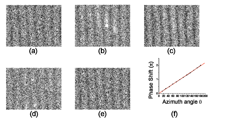
SummaryPolarization interferometry is normally not talked about at graduate level neither in theory and nor in laboratory. The students go with the concept that two different polarized light always result in a fringe free pattern. In this paper, a simple configuration similar to Michelson interferometer using polarized components is reported for the interference of two orthogonally polarized light in the class room. The measurement of the phase shift as a result of orientation of polarizer is performed. The theoretical expression is also presented for the fringe shift as a function of azimuth of the polarizer. The common method to realize relative phase shift in an optical beam of the Michelson interferometer in the class room is by physically changing the optical path of one of the arm of the interferometer either by translating mirrors or by introducing the optical surfaces in the form of glass plate1 in a controlled way. This phase shift is observed either in the form of fringe shift or some modification in the interference pattern. With one or more rotating polarizing components viz; polarizer, quarter wave plate or half wave plate, phase shift can also be observed2-5. In this paper, we report the effect of azimuth angle of polarizer in the output plane of two orthogonally polarized interfering beams from a heterodyne interferometric setup. The experimental set-up presented below is simple and can be handled by the graduate students independently. Experimental setup and TheoryA collimated laser beam was launched into an interferometric setup, as shown in fig. 1. The polarizer P1 was aligned at 450 ensures 50-50 splitting of light from polarizing beam splitter (PBS). The transmitted beam (only p-polarized light) from PBS passed through Quarter Wave Plate Q2 (QWP at 450) converted into right circularly polarized (r.c.p.) light. The r.c.p. beam reflected from mirror M2, became left circularly polarized (l.c.p.) and passed back through Q2. It turned into s-polarized light and reflected completely from PBS. The reflected beam (only s-polarized light) after passing through Q1, M1 and back from Q1 is converted into p-polarized light finally transmitted through PBS. So two orthogonal linearly polarized beams came out at the output of PBS. These orthogonal polarized beams produced fringe free pattern. To obtain the fringes, beams were passed through the third QWP Q3 and then through the polarizer P and the interference pattern was finally recorded on to CCD. Fig.1.Experimental setup for phase shifting interferometry; Q1, Q2 and Q3: quarter wave plates, M1, M1: mirrors, P1, P2: polarizers, PBS: polarizing beam splitter, CCD: charge coupled device.  For analyzing the effect of the azimuth angle of polarizer (and hence the phase shift) onto the interferograms, Q1 to Q3 were aligned at 450 with respect to polarization plane of the incident beam on the respective QWP’s and P2 was rotated. The resultant intensity at output plane can be shown to be given by6,7 Where spatial frequency ResultsThe recorded interference patterns for θ= 0°, 45°, 90°, 135°, 180° on to CCD are shown in the fig.2. (a), (b), (c), (d), (e) respectively. From fig.2, it is clearly observed that 180° rotation of the analyzer gives one fringe shift confirming an additional phase difference of 2π is developed between the two interfering orthogonal beams. The plot of measured phase shift versus the azimuth of analyzer (θ) is shown in fig.3 The plot confirm that the phase shift goes linearly with the azimuth θ of analyzer P2. ConclusionWe have experimentally observed the phase shift between the two orthogonal interfering beams using the set-up similar to Michelson interferometer and a quarter wave plate and an analyzer (rotating) at the output of the interferometer. We have recorded the interference pattern on to CCD and measured the fringe shift. The experiment can very well be performed using a photodiode mounted on the translation stage in place of CCD. AcknowledgementThis work is partially financed by CSIR, New Delhi, India, Scheme no. 3(831)/98-EMR-II. ReferencesD. Malacaara, Optical Shop Testing, John Wiley and Sons, New York
(1992). Google Scholar
P. Hariharan and M. Roy, Optics communications, 126 220
–222
(1996). https://doi.org/10.1016/0030-4018(96)00118-6 Google Scholar
Asundi A., Liu T., and Boay C. G., Applied Optics, 38 5931
–5935
(1999). https://doi.org/10.1364/AO.38.005931 Google Scholar
Kothiyal M.P. and Delisle C., Optica Acta, 33 787
–793
(1986). https://doi.org/10.1080/713822008 Google Scholar
Chyba T.H., Wang L.J., Mandel L., and Simon R., Optics Letter, 13 562
–564
(1998). https://doi.org/10.1364/OL.13.000562 Google Scholar
A S Patra and Alika Khare,
“Studies on two beam heterodyne interferometer,”
J of Optical tech, 72
(12),
(2005). https://doi.org/10.1364/JOT.72.000905 Google Scholar
D S Kilger, J W Lewis and C E Randel, Polarised light in optics, Acdemic press(1990). Google Scholar
|