|
|
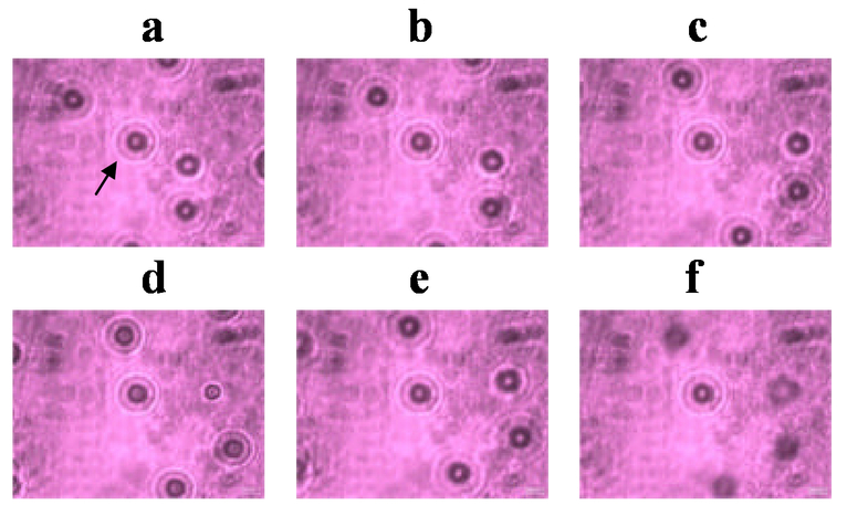
1.IntroductionOrbital angular momentum of light is a new fundamental concept in optics discovered only fifteen years ago [1]. Since then this form of angular momentum has been the subject of numerous studies [2]. It arises when a light beam is in a spatial mode with a helical wave-front. The transfer of orbital angular momentum has opened new applications in manipulation of matter with light using optical tweezers [3]. Orbital angular momentum has also been studied at the single-photon level [4], where it has created new possibilities in quantum information. It is becoming an increasingly important omission that optics textbooks, even modern ones, do not have discussions of orbital angular momentum. The purpose of this article is to start the process of filling this vacuum in optics instruction. Since orbital angular momentum appears in its purest form in high-order Laguerre-Gauss beams, it is logical to start by expanding the coverage of Gaussian beams in high-order modes [5]. The general topic of Gaussian beams is not dull. Quite contrary, it is rich with useful concepts and interesting wave physics. In this article we describe a way to introduce orbital angular momentum. We complement the theoretical description with laboratory experiences using optical tweezers. In Sec. 2 we give the conceptual narrative and in Sec. 3 we present laboratory demonstrations using optical tweezers. 2.Teaching methodologyOrbital angular momentum appears due to an azimuthal component of the linear momentum of the light present in beams with a helical wave-front. The transfer of orbital angular momentum to an object is easily observed using optical tweezers. Since optical tweezers can be explained in terms of momentum transfer of the light, we can incorporate a discussion of optical tweezers as a method to demonstrate momentum interactions between light and matter. This method may be also suitable to use in introductory physics. 2.1Momentum of lightWithin the framework of electromagnetic theory the linear momentum density of a light beam traveling in vacuum is where E and B are the electric and magnetic field vectors of the light, ?0 is the permittivity of vacuum, c is the speed of light, and S is the Poynting vector. It is convenient to express these quantities as time averages. The time average of the magnitude of the Poynting vector is also known as the irradiance I, so the average momentum per unit area is If a beam of light is incident on an absorptive object the force exerted by the light is given by F = P/c. Although the phenomenon can be explained fully in terms of electromagnetic theory, we can also appeal to the simplicity of the photon picture to explain light forces. If the instructor desires he or she can keep this description entirely from a classical electromagnetic perspective without invoking photons. However, so many optical phenomena are explained by electromagnetism that not taking the chance to talk about photons can be a missed opportunity. We must not fall prey to oversimplifying the photon as a spatially confined particle, as the quantum mechanical description is more sophisticated and rich. It is well accepted that light is composed of quanta or photons of energy E = hc/λ and momentum p = E/c. The momentum of a photon is very small compared to the momentum of macroscopic objects. For example, a 500-nm photon traveling in vacuum has a momentum p = 1.3 x 10⁻²⁷ kg m s−1. This is small even compared to the momentum of a single atom moving at thermal velocities. However, a light beam contains a large number of photons. A beam of 500-nm light with a power of 1 mW carries N = P/E = 2.5 x 10¹⁵ photons per second. When such a beam of light is absorbed by an opaque object, the object experiences an average force F = Np = 3.3 pN. This is a small force compared to macroscopic forces. However, it is larger than the weight of common microscopic objects. For example, a cube of size 5 μm and density 103 kg/m3 has a mass of 125 pg and weight of 1.2 pN. Thus, at this microscopic scale light can exert forces that can significantly affect the dynamics of an object. An optical tweezer is a microscope designed to send an intense beam of light from a laser to the sample being observed on the microscope slide. Objects are normally immersed in a liquid medium. Thus the force of light acting on a fully absorptive particle is F = Nnp, where n is the index of refraction of the medium. Our model object, a fully absorptive cube, is hardly realistic. Microscopic objects may have any shape and may reflect and refract the light. A more realistic object is a semi-transparent sphere. The force that light exerts on a latex sphere of 5-μm in diameter is only a fraction of the value that we calculated for a fully absorptive object. Ashkin studied this case and another more interesting situation: the forces due to a converging beam of light [6]. He found the very interesting result that the light focused towards spherical objects displaced from the center of the focal spot received a momentum recoil force toward focal point of the light. When the size of the object is larger than the wavelength of the light we can explain the force simply in terms of the recoil kicks that light exerts on the object. Thus, focused light exerts a trapping force on a spherical object. Ashkin showed that the maximum trapping force can be expressed as where Q is a parameter that depends on the geometry. Typical values of Q range between 0.01 and 0.5 [6–8]. Thus, trapping forces of the order of a few pN are very feasible [7]. This allows three-dimensional trapping of latex spheres of a few micrometers in diameter with not much difficulty. 2.1Angular MomentumA light beam can have two types of angular momentum. Spin angular momentum is due to the polarization of the light. It is specified by the parameter σ, where σ = ±1 for circular polarization, σ = 0 for linear polarization, and 0 < |σ| < 1 for all other states of elliptical polarization. Orbital angular momentum is present in wave-fronts with helical shape. In particular, Laguerre-Gauss beams are a class of beams with wave fronts with ℓ-intertwined helices. The orbital angular momentum of these beams is proportional to ℓ [1]. Figure 1 shows the wave-front of the Laguerre-Gauss beam with ℓ = 1. This beam has a characteristic “doughnut” profile owing to a phase that depends on the transverse angular coordinate. These types of beams can be introduced in an optical course as part of a treatment of Gaussian beams [5]. Fig. 1A drawing showing on the left the intensity profile of a Laguerre-Gauss beam, and on the right, the helical wave front of the lowest order mode carrying orbital angular momentum.  The angular momentum density of the light is given in terms of the linear momentum by The beam has angular momentum if it possesses an azimuthal component of the linear momentum Pϕ.. The component of the angular momentum density along the propagation direction z is then jz = rpϕ given by [9] where ω is the angular frequency of the light and u is a complex scalar function proportional to the electric field amplitude. It is interesting to note that for paraxial Gaussian beams the angular momentum has two independent contributions. The first one depends on ℓ and is the orbital angular momentum of the light. Notice that it depends on the square of the field amplitude, which means that the angular momentum is provided by the field of the wavefront. It is also provided by the amount of tilt of the wave-front, which is proportional to ℓ. The second term in Eq. (4) corresponds to the spin angular momentum. Thus a linearly polarized beam has no spin angular momentum, while right (σ = +1) or left (σ = −1) circularly polarized light have the largest magnitude of spin angular momentum. Note also that the spin angular momentum depends on the gradient of the field, so an infinite plane wave carries no spin angular momentum [9]. It is also interesting to note that the total angular momentum of the beam Jz divided by the total energy of the beam W yields [9] One photon would thus carry an angular momentum This result has prompted numerous studies of the angular momentum of single photons [4]. It also underscores how the effective angular momentum of a beam of light can be increased by using helical beams with high values of ℓ [10]. 3.Experimental Demonstrations with Optical TweezersThe optical tweezer is a laboratory tool that can be illustrative for demonstrating the momentum of light. Manipulating objects with light is so far removed from our everyday life that this experience can be quite fascinating as well. Optical tweezers are excellent for qualitative demonstrations. Quantitative experiences are difficult due to many experimental parameters that are hard to obtain accurately, such as friction with surfaces, intensity distribution of the light, etc. Optical tweezers are relatively easy to set up. A detailed description of many aspects of this device for use in undergraduate laboratories has been given before [7]. Here we describe the details of our setup, which is slightly different. On the left side of Fig. 2 we show a schematic of the apparatus. Key ingredients are a laser, a 100x microscope objective and a camera. The inverted configuration is the most desirable one because it allows easy trapping in the longitudinal direction. Fig. 2Schematic of an optical tweezer. It is an inverted microscope with a 100x objective and arranged so a laser beam is inserted to be focused at the sample on the slide.  A picture of the apparatus is shown on the right side of Fig. 2. The laser that we used was an argon-ion laser operating at 514.5 nm, with a maximum power of about 100 mW. Trapping can be attained with much lower power, but the extra power helps when setting up the optical tweezer for the first time. High power levels are now easily reached by other smaller lasers, such as diode-pumped solid state and diode lasers. We use a bright light emitting diode (LED) with a 10x microscope objective as a compact light source. The sample consists of polystyrene spheres of a few micrometers in diameter immersed in water. The sample is contained in a cell formed by a microscope slide, a layer of paraffin and a cover-slip. 3.1Linear Momentum Demonstrations.The trapping forces can be obtained by measuring the terminal velocity of the trapped sphere and using the viscous drag force where η is the viscosity (ηwater = 10−3 Pl), a is the radius of the sphere and v its velocity. For a 5-μm sphere moving at a velocity of 5 μm/s the drag force is 0.24 pN. A few qualitative examples of trapping are shown in Fig. 3. In the first row, frames (a, b, c) show transverse control: as the sample slide is moved one can see that the trapped sphere (5 μm in diameter) remains in place while the background spheres move to the right. Maximum speeds of about 60 μm/s with this setup yield a trapping force of about 3 pN and a trapping Q (Eq. 2) of about 0.01. Frames (d, e, f) show longitudinal control: as the slide is moved up the trapped sphere remains in place at the same focus. The focusing of the spheres in the background changes as they move in and out of the focal plane of the camera. This type of demonstration is straight forward to perform. 3.2Angular Momentum DemonstrationsIf the light carries angular momentum it can rotate the trapped object via momentum exchange. The torque produced by the optical beam can be related to the rotational frequency of the rotating object immersed in a viscous medium. When the object is a sphere the torque is given by [11] where ω is the angular frequency. To rotate objects via the spin angular momentum the light beam needs to be circularly polarized and the sample objects need to be either fully absorptive [12] or birefringent [13]. The latter has interesting physics: if the birefringent particle acts as a quarter-wave plate it can take spin angular momentum from a circularly polarized beam. This experiment was recently reported as an undergraduate laboratory [13]. We have been able to reproduce the experiments of Ref. [13] with not much difficulty. We used crushed calcite crystals immersed in water and put a quarter-wave plate in the path of the laser beam to change its linear polarization to circular. Inexpensive demonstrations of transfer of orbital angular momentum are difficult to perform because the inexpensive methods to produce beams carrying orbital angular momentum use inefficient binary forked gratings [5]. Efficient gratings in the form of phase holograms used in the early demonstrations [3] are not easy to make. An expensive alternative that is very popular today is to use of spatial light modulators [10]. Spiral phase plates are starting to become available, but in most cases they have to be special ordered. In an effort to try a new inexpensive method we followed the recent suggestion of making a phase plate from a wedged piece of Plexiglas [14]. We made a cut on a 1-mm thick square piece of Plexiglas (5-cm on the side), wedged the material at the cut, and passed the light through the wedged plate centered at the end of the cut, where the dislocation starts. Figure 4(a) shows a drawing of the wedged plate. Figure 4(b) shows an image of the beam after passing through the phase plate at a maximum wedge angle of about 13°. In order to diagnose the phase dislocation carried by the beam we sent the laser beam through a Mach-Zehnder interferometer, with the phase plate placed in one of the arms. We then imaged the resulting interference pattern. Figure 4(c) shows an image of the interference pattern. By the spiral shape of the pattern it is clear that the beam has a helical wave-front. From this and other patterns we estimate that the beam has an ℓ-value of between 4 and 5. From the shape of the beam we also gather that the value of ℓ is probably not an integer. As reported earlier, the helicity of the beam could be reduced by decreasing the wedge angle [14]. Fig. 4Images related to the phase plate. Frame (a) shows a sketch of the wedged phase plate. Frame (b) shows a laser beam profile after passing the phase plate. Frame (c) shows an interference pattern of the beam in (b) with a portion of the beam that did not go through the phase plate.  The frames on Fig. 5 show a demonstration of transfer of orbital angular momentum to a 10 μm sphere. The frames are separated by a time interval of about 30 s. The sphere was partially absorptive so the momentum transfer was not very efficient. We estimated a torque of 4 aN-m. 4.ConclusionsFifteen years ago a new form of angular momentum of light arising from the spatial mode of a light beam was discovered. This new form of angular momentum, called orbital angular momentum, has started new lines of research and found numerous applications. The fundamental character of orbital angular momentum demands that it be incorporated in optics instruction, even at the introductory level. Unfortunately modern textbooks have not yet incorporated these concepts. Following the lead of recent article [5], here we present ways in which the concept can be introduced. In addition, we present inexpensive undergraduate-level laboratory demonstrations of transfer of linear and angular momentum. 5.AcknowledgmentsThis work was funded in part from a grant from Research Corporation. N.Z. acknowledges funding from a Schlichting Fellowship of Colgate University. We also thank F. Cangemi for donating the argon laser and J. Noè, G. Caravelli and A. Jain for useful discussions. 6.6.ReferencesL. Allen, M.W. Beijersbergen, R.J.C. Spreeuw, and J.P. Woerdman,
“Orbital angular momentum of light and the transformation of Laguerre-Gaussian laser modes,”
Phys. Rev. A, 45 8185
–8189
(1992). https://doi.org/10.1103/PhysRevA.45.8185 Google Scholar
Optical Angular Momentum, Institute of Physics, Bristol
(2003). https://doi.org/10.1887/0750309016 Google Scholar
H. He, M.E.J. Friese, N.R. Heckenberg, and H. Rubinsztein-Dunlop,
“Direct observation of transfer of angular momentum to absorptive particles from a laser beam with a phase singularity,”
Phys. Rev. Lett., 75 826
–829
(1995). https://doi.org/10.1103/PhysRevLett.75.826 Google Scholar
A. Mair, A. Vaziri, G. Weihs, and A. Zeilinger,
“Entanglement of the orbital angular momentum states of photons,”
Nature (London), 412 313
–316
(2001). https://doi.org/10.1038/35085529 Google Scholar
E.J. Galvez,
“Gaussian beams in the optics course,”
Am. J. Phys., 74 355
–361
(2006). https://doi.org/10.1119/1.2178849 Google Scholar
A. Ashkin,
“Forces of a single-beam gradient laser trap on a dielectric sphere in the ray optics regime,”
Biophys. J., 61 569
–582
(1992). https://doi.org/10.1016/S0006-3495(92)81860-X Google Scholar
S.P. Smith, S.R. Bhalotra, A.L. Brody, B.L. Brown, E.K. Boyda, and M. Prentiss,
“Inexpensive optical tweezers for undergraduate laboratories,”
Am. J. Phys., 67 26
–35
(1999). https://doi.org/10.1119/1.19187 Google Scholar
J.E. Molloy and M.J. Padgett,
“Lights, action: Optical tweezers,”
Contemp. Phys., 43 241
–258
(2002). https://doi.org/10.1080/00107510110116051 Google Scholar
L. Allen and M.J. Padgett,
“The Poynting vector in Laguerre-Gaussian beams and the interpretation of their angular momentum density,”
Opt. Commun., 184 67
–71
(2000). https://doi.org/10.1016/S0030-4018(00)00960-3 Google Scholar
J.E. Curtis and D.G. Grier,
“Modulated optical vortices,”
Opt. Lett., 28 872
–874
(2003). https://doi.org/10.1364/OL.28.000872 Google Scholar
S. Oka, Rheology, 3 Academic Press, New york
(1960). Google Scholar
M.E. Friese, J. Enger, H. Rubinztein-Dunlop, and N.R. Heckenberg,
“Opical angular-momentum transfer to trapped absorbing particles,”
Phys. Rev. Lett., 54 1593
–1596
(1996). Google Scholar
D.N. Moothoo, J. Arlt, R.S. Conroy, F. Akerboom, A. Voit, and K. Dholakia,
“Beth’s experiment using optical tweezers,”
Am. J. Phys., 69 271
–276
(2001). https://doi.org/10.1119/1.1309520 Google Scholar
C. Rotschild, S. Zommer, S. Moed, O. Hershcovitz, and S.G. Lipson,
“Adjustable spiral phase plate,”
Appl. Opt., 43 2397
–2399
(2004). https://doi.org/10.1364/AO.43.002397 Google Scholar
|