|
|
1.INTRODUCTIONRadiometry is a system of language, mathematics and instrumentation used to describe and measure the propagation of electromagnetic (EM) radiation, including the effects on reflection, absorption, transmission and scattering by material substances. Many textbooks on electromagnetism1–7 and optical physics8–17 analyze these physical phenomena. In most of them the flux of energy associated to electromagnetic radiation is described in terms of the time average of the Poynting vector. This average is related to the square of the amplitude of the electric field and it is called “intensity” or “power density”. Likewise, the reflectance and transmittance at an interface separating two different media or the reflectance and transmittance of a plane parallel plate are expressed as a function of the incident, reflected and transmitted amplitudes of the electric field. The basic concepts of radiometry are introduced in most undergraduate optics textbooks9,14,17. However, these texts do not explain in adequate detail the relation between the “intensity” and the radiometric magnitude called irradiance neither express the reflectance and transmittance (either at an interface or of a plate) as a function of the radiometric magnitudes. Other example where the link between both views (optical and radiometric) is far from clear is the propagation of radiation through a lossy medium. The empirical law which describes this behavior is the well-known exponential decay of the radiation with the distance. EM textbooks describe this decrease of radiation studying the decay of the amplitude of electric field with the traveled distance. However, in Optics books, there is a great dispersion in the magnitudes used to describe the exponential law and it seems that exponential decay takes always the same form regardless of the radiometric magnitude. The purpose of this article is to contribute to a better understanding in the relation between the optical properties of materials and radiometric magnitudes, paying special attention to the physical concepts underlying the equations and trying to clarify what is somewhat messed. With that purpose in mind, in the next section radiometric magnitudes are briefly introduced. In section 3, the definitions of reflectance and transmittance at an interface and the propagation of an elemental beam of radiation immersed in a lossy medium are analyzed as a function of radiometric magnitudes. In section 4 we develop an example which is found in most textbooks: the optical properties of plane parallel plates. The reflectance and transmittance by calculating the power fluxes at each interface of the plate have been obtained and compared with the corresponding optical expressions found in optics textbooks. Finally, we end with the conclusions. 2.REMARKS ON RADIOMETRIC MAGNITUDESLet us begin regarding the principal magnitudes used in radiometry. They are displayed in Table I. The meanings of most of the quantities are shown by their defining equations. Table I.Radiometric magnitudes
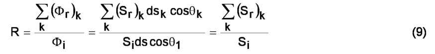
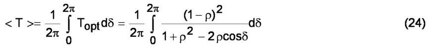
Usually, the definition of the intensity (I) as flux per unit of solid angle, is related to point sources. However, the definition can be applied to extended surfaces using the concept of radiance (L).The intensity of an infinitesimal surface ds at θ direction respect to its normal is defined as: where L is the radiance at ds. The definition of L, stated here for a source, is extended trivially for a detector and even for a ray, at any point along its path. For a source, radiance may vary from point to point, and for a fixed point, it may vary as a function of the direction. Radiance is the most general quantity for describing the propagation of radiation through space. Its importance stems mainly from the invariance theorem that states that, in any optical system, the radiance along the path of a ray is invariant18. Irradiance (E) is the most important quantity for describing radiation incident on or leaving a surface when it is not essential to describe the directional distribution of that radiation in detail. It does not discriminate, for example, between very collimated radiation and radiation that is impinging from all angles. In order to take into account the orientation of the elemental surfaces in which the radiation impinges with respect to the direction of propagation of the beam, we propose the use of what we have called perpendicular irradiance, S, which is the radiant flux which crosses a unit area perpendicular to the direction of the flow. The definition of this perpendicular irradiance would be: which matches the definition of the time average of the Poynting vector The perpendicular irradiance is equal to the irradiance when the surface element is perpendicular to the direction of propagation of the radiation. The propagation of the radiation is frequently studied for wave planes, that is, it would correspond to a parallel beam of radiation. In this case the surface is usually placed perpendicular to the direction of propagation (θ=0), so there is no distinction between irradiance and perpendicular irradiance and both magnitudes are identical to the radiation “intensity”. In this case, some Optics textbooks13,14,17 call correctly the “intensity” irradiance. The necessity of the perpendicular irradiance will be fully revealed when, in the next sections, we proceed to develop the reflectance and transmittance coefficients as functions of radiometric magnitudes as well as in the study of the propagation of radiation in a lossy medium. 3.PROPAGATION THROUGH AN INTERFACE SEPARATING TWO MEDIA AND A LOSSY MEDIUMWe examine the situation where a beam of radiation passes through a smooth surface separating two media with different refractive indices (n1 and n2). The geometric situation is shown in figure 1. We consider the extremely thin surface region of a perfectly smooth homogeneous and isotropic dielectric material. This interface is too thin to absorb significant quantities of the radiation incident on it. The radiation incident upon the interface is split into two parts: some is reflected and the rest is transmitted. The angles of incidence and reflection (θi and θr) are identical due to considering a specular reflection. The conservation of energy at the interface implies: Figure 1.Reflection and transmission of an incident beam irradiating an elemental surface ds at the interface. The angles of incidence and reflection are θi and θr (θi = θr) and θt is the angle of refraction.  where d2Φi is the element of the incident flux on the area ds, d2Φr is the element of the reflected flux and d2Φt is the element of the transmitted flux. The definitions of reflectance and transmittance for incident radiation of a given spectral composition, polarization and geometrical distribution are the ratios of the reflected or transmitted flux to incident radiant flux: Let’s write them as function of the different radiometric magnitudes. By applying the definition of the corresponding radiometric magnitude and performing simple geometrical and mathematical operations, we obtain the expressions of reflectance and transmittance at an interface as a function of radiometric magnitudes. The obtained expressions have been depicted in Table II. Note that reflectance is always the ratio of the reflected quantity to the incident one. On the contrary, transmittance expression changes with the radiometric magnitude. Similar relations to the expressions obtained for perpendicular irradiance have been found in some texts14,17 but they simply call S irradiance instead of perpendicular irradiance, what is a bit misleading. This is not the case of the text by Born9, where reflectance and transmittance are correctly defined as the ratio of irradiances Table II.Reflectance and transmittance at an interface as a function of radiometric magnitudes. Dependence with these quantities of the exponential decay of radiation in a lossy medium.  Suppose now we have some radiation leaving the surface element ds1 in the direction θ1 and another surface ds2 at x distance receiving this radiation flux from direction θ2. This is illustrated on Figure 2 (a). The flux entering the solid angle dω1 and leaving ds1 is d2Φ1. The flux received by ds2 is d2Φ2. If the two surfaces are immersed in lossy medium whose absorption of light results from linear response, the flux falls off exponentially with increasing the distance travelled in the medium: Figure 2.(a) A narrow beam of radiation that pass through the elemental areas ds1 and ds2. (b) Collimated beam propagating along the direction indicated by the arrows.(c) Point source: Radiation flux contained in the solid angle dω, dΦ = Idω.  here c is the attenuation coefficient which we suppose constant. This coefficient is the absorption coefficient when only absorbing effects are considered. If the surfaces were within a lossless medium, the flux would remain constant. By performing the appropriate calculations we can express this equation as a function of the radiometric magnitudes. The obtained equations have been included in Table II. If one has a collimated beam of radiation, that is, a bundle of approximately parallel rays propagating in the same direction with the associated flux contained in a small but measurable solid angle (Figure 2(b)), the irradiance is usually considered on a plane perpendicular to the ray. In this case, (ds1)⊥ = ds1 = (ds2)⊥ = ds2, the irradiance and the perpendicular irradiance, are identical and the simple exponential law is satisfied with all radiometric magnitudes. For the case of a point source immersed in a lossy medium (Figure 3(c)), it can be demonstrated that simple exponential law is satisfied if the magnitude chosen is the intensity of point source. If the magnitude used is the irradiance or the perpendicular irradiance the obtained equation is the familiar inverse-square law of radiation from a point source with the exception that the radiation is being attenuating by the medium. These results are summarized in Table III. Figure 3.Multiply reflected and transmitted beams in a parallel plate. The value of x is given by x=d/cosθ. The values of S in different positions of the beam have been plotted for incident Si =1. The expressions in parenthesis are the values of radiance (L) for incident Li =1.  Table III.Exponential law of the radiation propagating within an absorbing medium applied to the case of a collimated beam of radiation and a point source. R is the radius of the point source (x>>R). I0 is the intensity of the point source and E0 is the irradiance on the surface of the point source.  To end with this section, we would like to emphasize the importance of the different cases we have studied here in order to relate properly the physical situation with the appropriate radiometric magnitude. The next section illustrates an application of the equations we have just worked out (and displayed in Table II). 4.CASES STUDIES: PLANE PARALLEL PLATEA material bounded by two parallel interfaces defines an object that can reflect, transmit and absorb radiation incident on it. (Scattering processes are considered negligible). Let’s now obtain the optical properties of the plate by separating the power flux at each interface into an outgoing component and an incoming component. The reflectance, transmittance and absorptance of this object are defined respectively as the fraction of flux incident upon the object that is reflected, transmitted and absorbed by the object for defined directions of incidence and emergence, polarization state and wavelength. Let’s consider an unpolarized collimated beam of radiation of wavelength λ at the direction θ1 impinging on a plane parallel plate of a homogeneous and isotropic material of known thickness d and refractive index n which is surrounded by two media of index n1 and n2. The multiple reflections and transmissions of the incident beam are shown in Figure 3. The reflectance and transmittance of the left interface are ρ12, τ12, and ρ21, τ21, depending on the direction of the radiation (from n1 medium to n material or from the material to the n1 medium). In the same way, the reflectance and transmittance of the right interface are denoted by ρ23, τ23, ρ32 and τ32. The definitions of these interface magnitudes as a function of different radiometric magnitudes have been displayed in Table II. They can be determined by using Fresnel equations, which give the ratio of reflected (or transmitted) electric field amplitude to the incident one. Absorption is considered by taking into account that the flux of the ray propagating across the material will decrease according to the exponential law. 4.1Radiation viewSupposing that the incident flux is Φ1, the total reflectance R of the plate for this situation will be the ratio of the sum of all the fluxes emerging to the left of the incident flux: where the summatory is extended to the total number of interreflections in the material. Taking into account that the direction of reflected radiation is the same for all the emergent beams and that the angles of reflection and incidence are equal, the next relations are satisfied: cosθk = cosθ1 ∀k == dωk = dω1 ∀k ⇒ dωkdskcosθk = dω1ds cosθ1 ∀k (collimated beam dsk = ds ∀k). Applying these relations the reflectance can be expressed as a function of different radiometric magnitudes as follows: Therefore, the reflectance of the plate can be defined as the ratio of reflected to incident radiance or irradiance or perpendicular irradiance. Let’s perform the same calculations in order to obtain the transmittance of the plate. The total transmitance T of the plate will be the ratio of the sum of all the fluxes emerging to the right of the plane parallel plate: Now, the directions of the transmitted radiation are identical but they are different to the incident direction. The transmittance expressed as a function of different radiometric magnitudes will be: In this case dωkdsk cosθk = dω2ds cosθ2 ∀k and we can write: Applying the Snell laws n1sinθ1=nsinθ, nsinθ=n2sinθ2 and their differential equations the expression for the transmittance is reduced to: The equations for the transmittance as a function of irradiance and perpendicular irradiance will be: It can be observed that the expressions do not depend on the material refractive index (n) and the direction of the interreflections (θ) and that they are quite similar to the expressions for an interface. If the plate is surrounded by the same medium (i.e., n1=n2), the angles of incidence, reflection and transmission are equal and the reflectance (transmittance) can be defined as the ratio of reflected (transmitted) to incident radiometric magnitude, no matter which one is chosen. Let’s write the reflectance and transmittance of the plate (R and T) as a function of the reflectance, transmittance of the interfaces, ρ12, τ12, ρ21, τ21, ρ23, τ23, ρ32 and τ32. For that purpose, after choosing one radiometric magnitude we must apply its corresponding equations from Table II. Figure 3 shows the values obtained when using perpendicular irradiance (S) for the multiple reflections and transmissions between the two interfaces. If, for instance, radiance L were chosen, the values inside the material and at the right would be different from the S values displayed on figure 3, while the L values at the left of the figure would not change. The exponential law for the decreasing of radiation has been applied in the propagation of the beam inside the material. In this case this law does not change with the radiometric magnitude and takes its simplified expression (for instance, S2 = S1 exp(-cx) due to (ds1)⊥ = (ds2)⊥). By performing mathematical operations the following expressions for R and T are obtained: and the law of energy conservation implies that the absorptance A of the plate is given by A=1-R-T. In the case that the external medium be the same (n1=n2 and cosθ1=cosθ2), using Fresnel equations we get ρ23 = ρ21 = ρ12 =ρ, τ12τ21 = (1 - ρ)2, so that equations (16) are simplified to: If absorption processes are neglected (e-cx≈1), the result is: These magnitudes, that we call radiation reflectance and transmittance, only depend on ρ, that is, on the incident angle and the refraction indexes. 4.2Optical viewLet’s pay attention to the corresponding expressions that appear in many Optics textbooks for the last case (i.e., same external medium n1=n2); these books9,10,17 usually provide the total reflected and transmitted “intensity”, from which the reflectance and transmittance of the plate are easily calculated by performing the corresponding ratios. The reflection and transmission expressions of a plate when absorption processes are negligible are given by: where δ is the phase difference of two consecutive waves 4.3ComparisonLet’s compare now equations (18) and (21). Obviously, they are not the same. It can be noticed in equations (21) the dependence on the phase difference of two consecutive waves which implies that these expressions depend on the thickness of the plate. On the contrary, equations (18) do not depend on the thickness. As an example, we plot in Figure 4 both transmittances as a function of thickness for an uncoated calcium fluoride window at 486nm19 at two angles of incidence. Calcium fluoride has very low absorption at this wavelength, so the equations (18) and (21) are appropriate for this case. The curved lines are values obtained from eq. (21) and the straight line from eq. (18). As it can be seen, the optical values oscillate around those calculated from the radiation method and the oscillations change with the value of angle of incidence. The maximum dispersion of the Ropt and Topt values is ∆Ropt=∆Topt=4ρ/(1+ρ)2, which only depends on ρ. In Figure 5, it can be seen the dependence of both transmittances (Trad and Topt) and the dispersion ∆Topt with the angle of incidence. The dispersion is constant and small at low angles and increases strongly at higher angles of incidence. As we have noticed in the previous figure, the Topt values oscillate around the Trad values. How can we explain from a physical point of view these results? Figure 4.Transmittance values for an uncoated calcium fluoride window at 486 nm as a function of thickness at normal incidence (a) and at incidence θI=45° (b). The curved lines are the optical values and the black straight lines are Trad.  Figure 5.Trad, Topt (d=0.002m) and maximum dispersion of Topt as a function of angle of incidence for an uncoated calcium fluoride window at 486 nm. The dashed lines are the optical values and the black straight lines are Trad.  At first sight, and due to the fact that the optical equations (21) have been obtained taking into account interference processes, it may seem that performing some kind of averaging to the phase difference δ Hence, we conclude that the phase differences produced by the waves inside the plate can adopt any value, if:
By assuming that any of these effects take place, the Ropt and Topt could be averaged over all possible values of δ. If the following averages are performed: we obtain <R>=Rrad and <T>=Trad, that is, the optical equations averaged over δ become into the radiation expressions for reflectance and transmittance. So, clearly distinguishing these two types of magnitudes is very important not only from a basic physical point of view but from a practical viewpoint. Accurate reflectance and transmittance measurements are necessary for calibration spectrometers or for determination of the optical properties of materials. It is also important to distinguish both magnitudes in optics catalogues19, where the transmittances of the colored glass filters, the neutral density filters, the interference filters, the uncoated windows, etc., are shown. Evidently, the expressions for transmittance which describe the corresponding behaviours are different for each type of filter; therefore we must take into account the above considerations, such as, the roughness of the plate or the spectral bandwidth of the radiation in order to correctly interpret the given information. 5.CONCLUSIONS
ACKNOWLEDGEMENTSThis work was supported by the institutions Ministerio de Educación y Ciencia, Ministerio de Ciencia e Innovación, Universidad del País Vasco/Euskal Herriko Unibertsitatea, Gobierno Vasco/Eusko Jaurlaritza, Diputación Foral de Bizkaia/Bizkaiko Foru Aldundia, and the European Union 7th Research Framework Programme, under projects TEC2006-13273-C03-01, PSS-370000-2008-39, UE08/16, S-PE08CA01, DIPE08/24, and CE07/12-AISHA II, respectively. REFERENCESCheng D K,
“Field and Wave Electromagnetics,”
Addison-Wesley Publishing Company, Massachusetts
(1983). Google Scholar
Heald M A and Marion J B,
“Classical Electromagnetic Radiation,”
Saunders Collegue Publihshing)1995). Google Scholar
Jackson J D,
“Electrodinámica clásica,”
Alhambra Universidad, Madrid
(1980). Google Scholar
Lorrain P and Corson DR,
“Campos y ondas Electromagnéticos,”
Selecciones científicas, Madrid
(1979). Google Scholar
Reitz J R and Milford F J,
“Fundamentos de la teoría electromagnética,”
Unión tipográfica editorial hispano-americana, Mexico
(1972). Google Scholar
Ulaby F T,
“Applied Electromagnetics,”
New Yersey:Prentice Hall)1999). Google Scholar
Wangsness R K,
“Campos Electromagnéticos,”
Ed. Limusa, Mexico
(1987). Google Scholar
Annequin R and Boutigny J,
“Optica,”
Ed. Reverte, Barcelona
(1976). Google Scholar
Born M and Wolf E,
“Principles of Optics,”
Pergamon Press, Oxford
(1980). Google Scholar
Casas J,
“Optica,”
cooperativa de artes gráficas, Zaragoza
(1985). Google Scholar
Ditchburn R W,
“Optica,”
Ed. Reverte, Barcelona
(1982). Google Scholar
Guenther R,
“Modern Optics,”
John Wiley&Sons)1990). Google Scholar
Heavens O S and Ditchburn R W,
“Insigth to Optics,”
Ed. Wiley)1991). Google Scholar
Hecht E and Zajac A,
“Optica,”
Addison-Wesley Iberoamericana, Wilmington USA: Ed
(1986). Google Scholar
Jenkins F A and White H E,
“Fundamentals of Optics,”
Ed McGraw-Hill)1981). Google Scholar
Landsberg G S,
“Optica,”
Ed Mir, Moscu
(1984). Google Scholar
Pedrotti F L and Pedrotti L S,
“Introduction to Optics,”
Prentice Hall, New Yersey
(1993). Google Scholar
Nicodemus FE,
“Radiance,”
Am. J. Phys, 31 368
–377
(1963). https://doi.org/10.1119/1.1969512 Google Scholar
Newport Resource Catalog,
(2008). Google Scholar
|