|
|
|
|
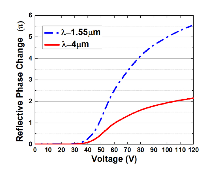
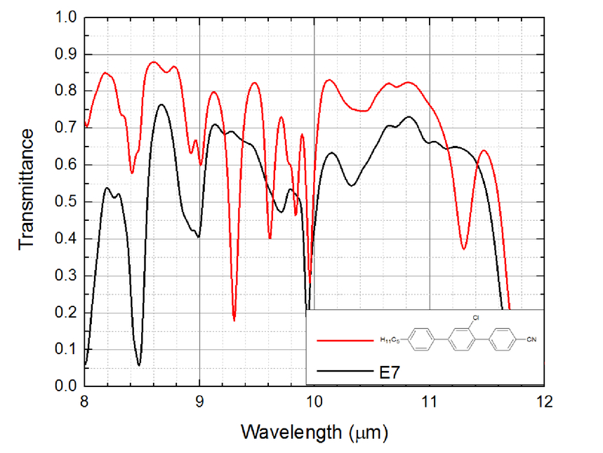
1.INTRODUCTIONIn addition to amplitude modulation (e.g., displays [1]), liquid crystals (LCs) have also found useful applications for phase modulation [2], such as spatial light modulators for laser beam steering [3], adaptive optics in the mid-wave infrared (MWIR 3~5µm) and long-wave infrared (LWIR 8~12µm) regions [4], as well as phase shifters in the microwave [5, 6] and terahertz regions [7–9]. For IR applications, besides high birefringence (Δn), low viscosity (γ1), and large dielectric anisotropy (Δε), low absorption is another critical requirement. Numerous molecular vibration bands exist in the IR region [10]. To steer a high power laser beam in the IR region, the absorption of LC must be minimized because the absorbed light is converted to thermal energy, which in turn heats up the LC material and causes spatial phase non-uniformity [11]. In the extreme case, if the resultant temperature exceeds the LC’s clearing point (Tc), then the light modulation capability vanishes completely. Therefore, the LCs employed should be designed to have low absorption and a high Tc. Therefore, three approaches are considered for shifting the vibration bands outside the spectral region of interest: (1) deuteration, (2) fluorination, and (3) chlorination. The deuteration shifts the CH vibration bands to a longer wavelength by In this paper, we describe some chlorinated LC compounds and we have formulated a eutectic mixture with a wide nematic temperature range (−40°C→85°C). The mixture is highly transparent (transmittance >98%) in the MWIR region. To achieve fast response time, we demonstrated a polymer network liquid crystal with 2π phase change at MWIR and the response time is less than 5ms. For LWIR applications, we prepared a high Δn chlorinated LC with high transmittance at λ=8~9μm and λ=10~11 μm. 2.LC COMPOUNDS AND MIXTURES FOR MWIRA p-terphenyl core unit is usually employed to obtain high birefringence. The chemical structures of chlorinated LC compounds are reported in [17]. To lower the melting point, we formulated a eutectic mixture (called IR-M1) from these three compounds and it exhibits an enantiotropic phase with Tc=68°C. In addition, to widen the nematic temperature range, we doped 10 wt% of chlorinated cyclohexane terphenyls, whose nematic temperature range is over 100°C. The final mixture is designated as IR-M2. Remarkably, the melting point of mixture IR-M2 drops to less than −40°C (limited by our DSC) and its clearing point is 85°C. We kept IR-M2 at −40°C for 3 hours and it did not crystalize. Thus, IR-M2 exhibits a wide nematic range including room temperature. 2.1BirefringenceBirefringence was measured through phase retardation of a homogeneous cell sandwiched between two crossed polarizers [18]. The cell gap was controlled at ~5μm. A 1 kHz square-wave AC voltage signal was applied to the LC cell. A tunable Argon-ion laser (λ=457nm, 488nm, and 514nm), a He-Ne laser (λ=633nm), and a semiconductor laser (λ=1550nm) were used as light sources. To determine the birefringence at MWIR region, we measured the dispersion curve as shown in Fig. 1. The blue line represents the fitting curve with single-band birefringence dispersion model [19, 20]: Fig. 1.Birefringence dispersion of IR-M2 at room temperature: the black dots are measured data and the dash line is a fitting with Eq. (1).  where G is a proportionality constant and λ* is the mean resonance wavelength. Through fitting, we obtained G=3.37μm− 2 and λ* =0.240μm. The birefringence of IR-M2 keeps relatively high (Δn~0.194) in the MWIR region. To achieve 2π phase change at λ=4μm, the required cell gap is 20.62μm. High Δn enables a thin cell gap to be used for achieving a certain phase change, which in turn leads to fast response time and high transmittance. 2.2Visco-elastic constantFrom the response time measurement of the LC cell, we can extract the visco-elastic coefficient (γ1/K11) [21]. Figure 2 depicts the visco-elatic constant at different temperatures, in which black dots are experimental data and blue dash line is the fitting curve with following equation: Fig. 2.Temperature dependent visco-elastic coefficients of IR-M2: black dots are measured data and blue dash line is fitting with Eq. (2) at λ=633nm.  In Eq. (2), A is a proportionality constant, kB is the Boltzmann constant, Ea is the activation energy, and β is the material constant. Through fitting, we obtained Ea=525meV for IR-M2. The large activation energy results from the heavy chlorine atoms and terphenyl structures. The estimated optical response time is ~800ms. 2.3MWIR transmittanceTo measure the IR transmittance, we filled IR-M2 to a LC cell with two sodium chloride (NaCl) substrates and measured the transmittance with a Perkin Elmer Spectrum One FTIR Spectrometer. Besides, the LC molecules are aligned homogeneously. To achieve 2π phase change at λ=4μm, the required cell gap is 20.62μm. We fabricated an LC cell with a gap of d=21μm and Figure 3 depicts the measured transmittance of IR-M2 at room temperature from 2μm to 12μm. In the 3.8μm → 5μm region, the transmittance is ~98%. This is because the vibration peaks resulting from C-Cl bonds are shifted to beyond 12.5 μm and the overtone is outside the MWIR window as well. There is a strong absorption peak centered at 3.4μm resulting from the C-H stretching in the alkyl chain and aromatic rings, which are unavoidable since these C-H bonds are basic elements of organic compounds that exhibit a mesogenic phase. Besides, C-H bond vibrations contribute to the strong absorption at longer wavelength as well. In order to achieve a 2π phase change at LWIR region, e.g. λ=10.6μm, the required cell gap is ~2x larger than that at MWIR region and the transmittance at λ=10~11μm is expected to decrease to ~70%. This loss is too large, and other high Δn LC compounds should be considered, as will be discussed later. 2.4Dielectric anisotropyIn addition to cleaning up the MWIR absorption, the two chloro groups also contribute to dielectric anisotropy. To determine the dielectric constants of IR-M2, we measured the capacitance of a homogeneous cell and a homeotropic cell using an HP-4274 multi-frequency LCR meter and found Δε =6.89 (ε∥ =10.7, ε⊥ =3.84) at 23°C and f=1 kHz. 2.5Polymer network liquid crystal at MWIRBesides, we fabricated a polymer network liquid crystal (PNLC) to achieve fast response time. Some fluorinated cyano-terphenyls are mixed with IR-M1 to increase the dipole moment and reduce the operation voltage. The chemical structures of cyano-terphenyls and fabrication process are reported in [16]. To characterize the electro-optical properties of our PNLC cells, we measured the VT curve at λ=1.55μm because our ITO glass substrates are not transparent and its transmittance drops to 60% at λ=4μm. The PNLC cell was sandwiched between two crossed polarizers, with the rubbing direction at 45° to the polarizer’s transmission axis. We converted the measured VT curve to a voltage-dependent phase (VP) curve for each sample. Figure 4 shows the VP curve for the PNLC with 5 wt% RM257. According to the dispersion curve, the birefringence is insensitive to the wavelength in the IR region. Therefore, we converted the VP curve from λ=1.55μm to λ=4μm. To measure the response time of a PNLC, we removed the biased voltage spontaneously at t=0. The biased voltage was 105V, corresponding to V2π at λ=4μm. The measured phase decay time (from 100% to 10%) is 3.6ms, which is more than 100X faster than the conventional nematic LC phase modulators. The faster response time can be achieved by increasing monomer concentration, but the tradeoff is the incresased operation voltage. 3.LC COMPOUND FOR LWIRThe transmittance (T) of a liquid crystal layer can be expressed as: where α is the absorption coefficient and d is the cell gap or optical path length. Therefore, to minimize the absorption loss while keeping a required phase change (δ=2πdΔn/λ) in LWIR region (λ=8~12μm), two approaches can be considered: 1) To reduce the absorption coefficient α by substituting the C-H in-plane bending vibrations in the aromatic rings, and 2) to employ a high Δn LC to reduce the required cell gap or optical path length. Chlorinated cyano-terphenyls possesses a high birefringence at visible region (Δn~0.35 at λ=633nm) because the combination of the terphenyl core and the cyano group elongate the conjugation length. Based on the birefringence dispersion model, Δn drops about 10~20% as the wavelength increases from the visible to IR. Here, we suppose Δn~0.29 at λ=10.6μm and the required cell gap to get a 2π phase change is d=36.6μm. We also include a commercial LC mixture E7 for comparison. Based on the birefringence dispersion of E7: G=3.06μm−2 and λ* =0.250μm, we find Δn~0.19 at λ=10.6μm. Thus, the required cell gap at this wavelength is 55.8μm. Figure 5 depicts the measured transmittance in the LWIR. Chlorinated cyano-terphenyls compound (chemical structure is shown in Fig. 5) with higher birefringence and thinner cell gap shows a much higher transmittance than E7 at both λ=8~9μm and 10~11μm. Some resonance bands of compound 6 are found at λ=9~10μm because of C-H in-plane vibration resulting from tri-substituted and di-substituted phenyl rings. While the four components in E7 just have di-substituted phenyl rings. Though the CN polar group shows a relatively sharp and strong resonance peak at ~4.48μm, it does not degrade the transmittance in the LWIR region. Similar to IR-M2 for MWIR, we can also formulate eutectic mixtures consisting of homologs of chlorinated cyano-terphenyls for LWIR applications. 4.CONCLUSIONSome recently developed chlorinated liquid crystal compounds and mixtures are reported. The chlorinated mixture shows wide nematic temperature range, low absorption loss and relatively high birefringence in the MWIR region. To achieve fast response time, we demonstrated a polymer network liquid crystal with 2π phase change at MWIR and response time less than 5 ms in reflective mode. Beside, a chlorinated cyano-terphenyl LC compound has been proposed to achieve high transmittance at LWIR region with keeping 2π phase change. ACKNOWLEDGMENTSThe authors are indebted to Office of Naval Research for the financial support under contract No. N00014-13-1-0096 and AFOSR under contract No. FA9550-14-1-0279. REFERENCESSchadt, M.,
“Milestone in the history of field-effect liquid crystal displays and materials,”
Jpn. J. Appl. Phys, 48 03B001
(2009). Google Scholar
Peng, F., Xu, D., Chen, H., and Wu, S.-T.,
“Low voltage polymer network liquid crystal for infrared spatial light modulators,”
Opt. Express, 23
(3), 2361
–2368
(2015). Google Scholar
McManamon, P.F., Dorschner, T.A., Corkum, D.L., Friedman, L.J., Hobbs, D.S., Holz, M., Liberman, S., Nguyen, H.Q., Resler, D.P., and Sharp, R.C.,
“Optical phased array technology,”
Proc. IEEE, 84
(2), 268
–298
(1996). Google Scholar
Wu, S.T., Margerum, J.D., Meng, H.B., Hsu, C.S., and Dalton, L.R.,
“Potential liquid crystal mixtures for CO2 laser application,”
Appl. Phys. Lett, 64
(10), 1204
–1206
(1994). Google Scholar
Dolfi, D., Labeyrie, M., Joffre, P., and Huignard, J.P.,
“Liquid crystal microwave phase shifter,”
Electron. Lett, 29
(10), 926
–928
(1993). Google Scholar
Lim, K.C., Margerum, J.D., and Lackner, A.M.,
“Liquid crystal millimeter wave electronic phase shifter,”
Appl. Phys. Lett, 62
(10), 1065
–1067
(1993). Google Scholar
Hsieh, C.-F., Pan, R.-P., Tang, T.-T., Chen, H.-L., and Pan, C.-L.,
“Voltage-controlled liquid-crystal terahertz phase shifter and quarter-wave plate,”
Opt. Lett, 31
(8), 1112
–1114
(2006). Google Scholar
Lin, X., Wu, J., Hu, W., Zheng, Z., Wu, Z., Zhu, G., Xu, F., Jin, B., and Lu, Y.,
“Self-polarizing terahertz liquid crystal phase shifter,”
AIP Adv, 1
(3), 032133
(2011). Google Scholar
Dąbrowski, R., Kula, P., and Herman, J.,
“High birefringence liquid crystals,”
Crystals, 3
(3), 443
–482
(2013). Google Scholar
Wu, S.-T.,
“Absorption measurements of liquid crystals in the ultraviolet, visible, and infrared,”
J. Appl. Phys, 84
(8), 4462
–4465
(1998). Google Scholar
Wu, S.-T.,
“Infrared properties of nematic liquid crystals: an overview,”
Opt. Eng, 26
(2), 120
–128
(1987). Google Scholar
Wu, S.-T., Wang, Q.-H., Kempe, M.D., and Kornfield, J.A.,
“Perdeuterated cyanobiphenyl liquid crystals for infrared applications,”
J. Appl. Phys, 92
(12), 7146
–7148
(2002). Google Scholar
Mistry, B., A Handbook of Spectroscopic Data Chemistry: UV, IR, PMR, CNMR and Mass Spectroscopy, Oxford2009). Google Scholar
Chen, Y., Xianyu, H., Sun, J., Kula, P., Dabrowski, R., Tripathi, S., Twieg, R.J., and Wu, S.-T.,
“Low absorption liquid crystals for mid-wave infrared applications,”
Opt. Express, 19
(11), 10843
–10848
(2011). Google Scholar
Peng, F., Chen, Y., Wu, S.-T., Tripathi, S., and Twieg, R.J.,
“Low loss liquid crystals for infrared applications,”
Liq. Cryst, 41
(11), 1545
–1552
(2014). Google Scholar
Peng, F., Chen, H., Tripathi, S., Twieg, R.J., and Wu, S.-T.,
“Fast-response infrared phase modulator based on polymer network liquid crystal,”
Opt. Mater. Express, 5
(2), 265
–273
(2015). Google Scholar
Peng, F., Lee, Y.-H., Chen, H., Li, Z., Bostwick, A.E., Twieg, R.J., and Wu, S.-T.,
“Low absorption chlorinated liquid crystals for infrared applications,”
Opt. Mater. Express, 5
(6), 1281
–1288
(2015). Google Scholar
Wu, S.-T., Efron, U., and Hess, L.D.,
“Birefringence measurements of liquid crystals,”
Appl. Opt, 23
(21), 3911
–3915
(1984). Google Scholar
Wu, S.T., Efron, U., and Hess, L.D.,
“Infrared birefringence of liquid crystals,”
Appl. Phys. Lett, 44
(11), 1033
–1035
(1984). Google Scholar
Wu, S.-T.,
“Birefringence dispersions of liquid crystals,”
Phys. Rev. A, 33
(2), 1270
–1274
(1986). Google Scholar
Wu, S.-T. and Wu, C.-S.,
“Experimental confirmation of the Osipov-Terentjev theory on the viscosity of nematic liquid crystals,”
Phys. Rev. A, 42
(4), 2219
–2227
(1990). Google Scholar
|