|
|
1.Scope of the experimentThis apparatus allows our students to measure the modulation transfer function of a camera lens with f‘= 25mm and Nmin = 0.95 which is used with a CMOS chip with 5472 × 3648 pixels and a pixel size of 2.4 µm. Such a delicate measurement is also a good opportunity to demonstrate several key aspects of optical instrumentation, namely, the implementation of a linear source for a given optical system, the impact of the finite size of the source on the measurement, and the choice of the optical elements to image the response of the studied lens on the camera. The linear source is a practical solution to measure the MTF with light sources which would not be bright enough for use with a point source. The MTF thus measured is in 1D, orthogonally to the direction of the line. This can be proven as follows, given a source S(x, y) = δ(x).C and a lens of diameter a: The response of the objective can be expressed as the square of the Fourier transform of the product of the source with the aperture of the lens R2(kx, ky), with (kx, ky) the spatial frequencies associated with resp. (x,y). Recalling This corresponds to the Linear Spread Function (LSF). The Fourier Transform of the LSF then gives the 1D MTF in the y-direction. 2.Experimental apparatusThe setup shown on Figure 2 goes as follows:
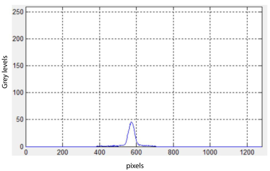
3.Preliminary considerationsPrior to diving into the experiment, the students must work out the best theoretical specifications of the studied camera lens: the MTF cut-off frequency fc and the size of the point spread function ΦAiry. For λ = 630 nm, N = 0.95 and γ the magnification of the optical system: ΦAiry ≈ λ N ≈ 1.5 µm Because the camera has a pixel size of 2.4 µm, the system (lens + camera) is thus theoretically limited by the pixel size (fc,chip = 417 mm–1 ). From ΦAiry they can deduce the maximum size of the point source d, given the optical system. d ≪ γ ΦAiry Given that the focal length of the collimator is 500 mm and that of the objective is 25 mm, the magnification γ = 20. Therefore, d ≪ 30 µm in order to study the camera lens at full aperture. The students are then asked to work out the sampling spatial frequency of their measurement apparatus to verify that the combination of the x40 microscope objective and the CMOS chip with 1.3 × 10⁶ square, 5.3 µm pixels is appropriate to measure the MTF of the camera lens. A quick calculation yields a sampling frequency of about 7500 mm –1, which is clearly sufficient. Another important point concerns the choice of the collimator and the microscope objective. It goes without saying that the two must be devoid of aberrations. Moreover, the collimator aperture must be significantly larger than that of the camera lens, and the object numerical aperture of the microscope objective must obviously be greater than the image numerical aperture of the lens not to limit the measurement. 4.Observations and measurementsBefore making use of the camera and the analysis software, it is informative to make visual observations of the linear spread function. This allows the students to get an intuitive grasp of the aberrations, estimate the size of the LSF and for which aperture size the objective starts to be diffraction-limited. A more in-depth quantitative analysis is then carried out using the Matlab software provided, the interface of which is shown on Figure 3. After a careful calibration of the magnification of the imaging of the focal spot onto the camera and tuning the exposure time to an appropriate value, the students can view the LSF (e.g. Figure 4) and the measured MTF (e.g. Figure 5) in real time. This allows them to identify the maximum aperture for which the camera lens is diffraction-limited and to quantify the effects of the different aberrations, for example the longitudinal displacement of the best focus for different aperture sizes or for different wavelengths, on- and off-axis. 5.ConclusionWe have shown an undergraduate lab setup designed to perform the measurement of the modulation transfer function in 1D of a camera lens. The use of a slit as a linear source allows to work with sources that would not be bright enough for use as a point source. Moreover, the adjustability of the slit width is educationally interesting as the students can directly see the impact of the size of the source on the LSF and subsequently on the measured MTF which they can visualize in real time thanks to a simple GUI. The aberrations of the camera lens can then be studied quantitatively in terms of the MTF. They can then identify that the objective is diffraction-limited from N = 8. |