|
|
|
|
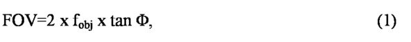
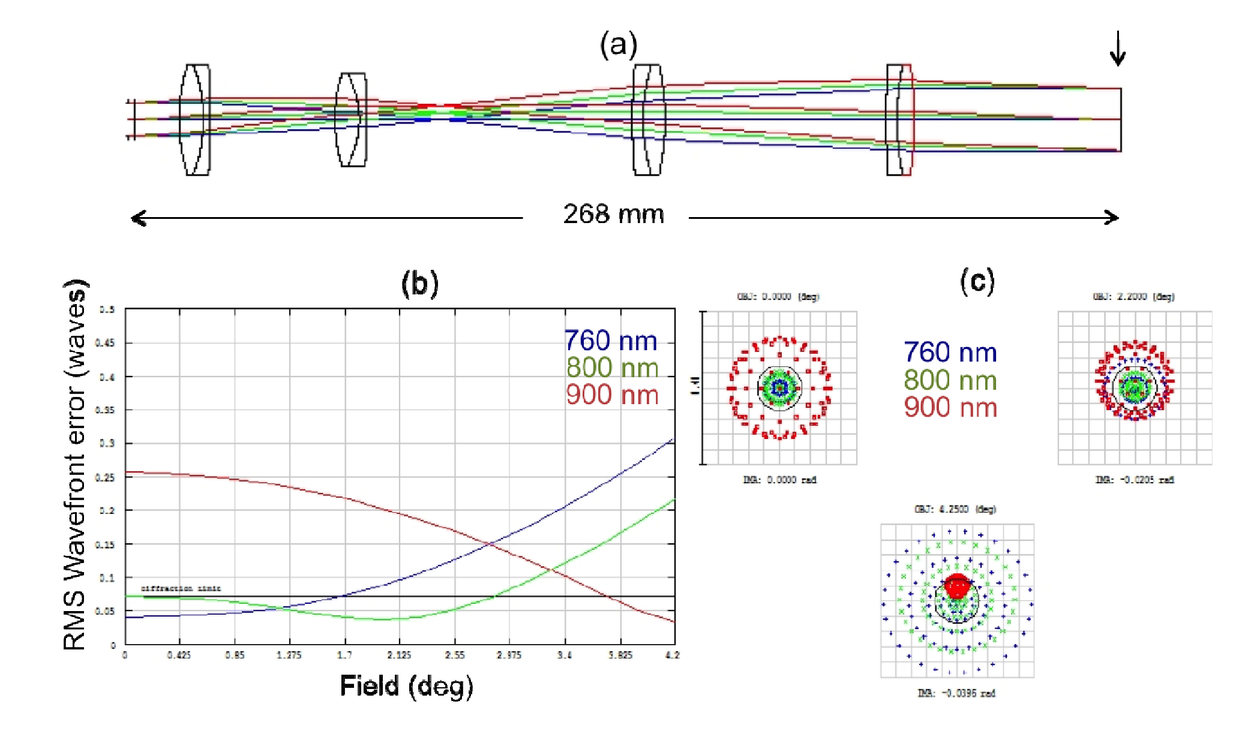
1.INTRODUCTIONIn vivo multiphoton microscopy (MPM) is emerging as an important research and clinical tool for label-free imaging in human skin. The clinical applications of in vivo label-free MPM span from skin cancer detection and diagnosis [1-4], to characterizing and understanding keratinocyte metabolism [5], skin aging [6, 7], pigment biology [8-10], and cosmetic treatments [11-13]. MPM is based on laser-scanning microscopy, a technique that utilizes a focused laser beam that is raster-scanned across the sample to create high-resolution images. A 3D-view of the skin can be reconstructed by scanning at multiple depths. Importantly, high-resolution imaging is combined with a label-free contrast mechanism. MPM contrast in skin is derived from second harmonic generation (SHG) of collagen and two-photon excited fluorescence (TPEF) of tissue components such as the co-factors NADH and FAD+, elastin, keratin, and melanin. Clinical examination crucially relies on the ability to quickly examine large tissue areas and rapidly zoom in to regions of interest. Skin lesions often show irregularity in color and appearance, especially when they start to progress towards malignancy. Imaging of large field of views (FOVs) and automatic translation of the imaging area are critical in the assessment of the entire lesion to avoid false negative diagnosis. Commercial clinical microscopes based on MPM and reflectance confocal microscopy (RCM) have implemented automatic translation of the imaging area [2, 14]. However, the initial FOV is limited to less than 0.5x0.5 mm2 and thus, assessing large areas of tens of mm2 at different depths may be time consuming and not feasible for clinical use. In an ideal system large FOV and automatic translation of the imaging area would be complemented by fast image acquisition and high detection sensitivity in order for such a system to be of practical utility and efficient use for fast full assessment of skin lesions. Advances in the development of NLOM-based microscopes that can image large FOVs have been recently made by several research groups [15, 16]. Tsai et al. reported on developing an NLOM-based system that can image up to 80 mm2 at a maximum speed of 5mm/ms by trading-off lateral resolution (between 1.2 μm and 2 μm across the entire FOV) [16]. This microscope was applied for imaging resting-state vasomotion across both hemispheres of a murine brain through a transcranial window and histological slides without the need to stich adjacent imaging areas. Negrean and Mansvelder presented an in-depth optimization study of scan and tube lens designs for minimizing optical aberrations associated with large angle scanning [17]. Both aforementioned studies used conventional galvanometer scanning. Higher scan speeds provided by resonant scanner as the fast axis and conventional galvanometer as the slow axis have been previously implemented in MPM-based systems for several applications [18-21], including skin imaging [19, 21]. In this work, we demonstrate that MPM skin imaging can be performed rapidly on large areas without compromising resolution. The MPM-based imaging system we developed features rapid acquisition capability of large FOV of 800x800 μm2, with sub-micron spatial resolution. Ex vivo images of normal human skin were acquired to assess the performance of the system. 2.BASIC DESCRIPTION OF THE MICROSCOPE AND MAIN DESIGN CONSIDERATIONSThe MPM system includes a fast galvanometric scanner, relay optics, a beam expander and a high NA objective lens. The selection of the objective determines the main optical design considerations of the microscope. We have chosen to optimize the system based on the 25x, 1.05 NA water immersion lens from Olympus (XLPL25XWMP), one of the premier tissue imaging objectives that features a long working distance of 2 mm. This objective has a focal distance of 9.6 mm (assuming a tube lens focal length of 180 mm used by Olympus) and an entrance pupil diameter of approximately 15 mm. We describe below in detail the main components of the system. 2.1Implementation of fast imaging acquisitionOur design is based on a resonant scanner (Cambridge Technology), which operates at 4 kHz and supports a frame rate of 10 frames/s for an image of 800 x 800 pixels. Once relevant areas have been identified, it is possible to take high-density pixel maps of 1600 x 1600 pixels at a rate of 0.2 seconds per frame. However, high signal-to-noise ratio (SNR) images require averaging of several frames. We found that averaging 4 frames is sufficient for the fast scanning mode, which we use for fast visualization of features in the sample, while average of 8 frames is necessary for the slow scanning mode, employed for recording high SNR images. Therefore, the fast scanning mode used has a rate of 0.4 seconds per frame (average of 4 frames of 800x800 pixels), while the slow scanning mode has a rate of 1.6 seconds per frame (average of 8 frames of 1600x1600 pixels). Along with the fast mechanical scanner, high-speed acquisition electronics is needed to capture the data. We use a high speed 4 channel 14-bit analog-to-digital (A/D) converter to process the data. The A/D card features a sampling rate of 120 MS/s and a 1GS memory, more than sufficient to acquire imaging data at 10 frames/s. The card is controlled through a C++ based software and a GUI for the final user-friendly version of scanning software (Intelligent Imaging Innovations, Denver, CO). The useful aperture for the resonant scanner is 12 mm x 9.25 mm, while for the right hand Y mirror is 10 mm. 2.2Implementation of a wide field of view (FOV)2.2.1Optical design considerationsIn a laser-scanning microscope, the FOV is determined by the objective focal length (fobj) and the scanning angle at the back aperture of the objective (Φ): where Φ is measured from the optical axis and thus, it is half of the full scanning angle. Large FOV is achieved for long objective focal lengths and large scanning angles. Both of these parameters result in limited spatial resolution, as long focal lengths correspond to low magnification and low NA objectives, while large scanning angles lead to optical aberrations such as coma and astigmatism. Once the focal length is determined based on the selection of the objective, the FOV is limited by the scanning angle. The scanning angle of the mirrors depends on the magnification of the system. Low magnification is required to minimize the scanning angle and optical aberrations such as coma and astigmatism. The objective entrance pupil diameter determines the beam size before objective. The laser beam has to overfill the back aperture of the objective in order to aim for the highest spatial resolution possible allowed by the objective NA. This task is performed by a beam expander, which consists of scan and tube lens elements. The beam expander of our system has a 1.8x magnification, which was determined by the maximum beam diameter of 9 mm allowed by the scanning mirror and the objective entrance pupil diameter, 15 mm. Therefore, a FOV of 0.8 x 0.8 mm2 would require an angle Φ of 2.4° (Eq.1) at the back aperture of the objective and a 4.3o scanning angle of the mirrors. These were the parameters used for designing the beam expander. A common limitation of the FOV in conventional laser-scanning microscopes, where the scanning mirrors are placed in proximity, is related to the motion of the laser beam at the back aperture of the objective. This is due to the beam displacement by the first mirror on the second mirror, which for large angles, can lead to vignetting and reduction of the FOV [22, 23]. To address this limitation, we employed a relay lens system between the scanning mirrors. We built the relay and beam expander systems by using off-the-shelf achromat lenses as a cost-effective solution. The lenses were selected such that the root mean square (RMS) wavefront error resulted from the system was not larger than 0.07 λ, a criterion associated with “diffraction-limited” performance (Maréchal criterion). Simulation and optimization of both the beam expander and the relay imaging systems were carried out using a computer-aided design software (ZEMAX, Radiant ZEMAX LLC). We performed the optimization for a maximum scanning angle of 4.3°, a Gaussian beam diameter of 9 mm (1/e2) and a beam expander magnification of 1.8. These parameters lead to a beam diameter of 16.2 mm after the expander, overfilling the back aperture of the objective (XLPL25XWMP, Olympus) and to a FOV of 800x800 μm2. The primary optimization wavelength was 800 nm, the wavelength of interest for our application, skin imaging. We describe below in detail the components and the overall performance of the relay lens system and the beam expander. 2.2.2Relay lens systemWe selected 4 commercially available achromat lenses to form a 1:1 relay lens imaging system (026-1130, Optosigma and PAC046, Newport - 2 pairs of each). The RMS wavefront error corresponding to 800 nm is 0.06. The RMS wavefront distribution with respect to the field indicates that more than 2/3 of the FOV is diffraction-limited (Fig 1b). 2.2.3Beam expanderThe beam expander imaging system consists of four doublet achromatic lenses (AC300-080-B Thorlabs; PAC046, Newport; 026-1180 and 026-1220 Optosigma). The RMS wavefront error corresponding to 800 nm is 0.07. The RMS wavefront distribution with respect to the field indicates that more than 2/3 of the FOV is diffraction-limited (Fig 2b). 3.MPM IMAGING SYSTEM PERFORMANCEWe used 0.2 µm and 0.5 µm yellow-green (505/515) fluorescent beads (Molecular Probes, Eugene, Oregon) for measuring the lateral and the axial resolution, respectively. We measured a lateral PSF of 0.5 ± 0.2 µm and an axial PSF of 2.5 ± 0.4 µm (full-width half maximum of Gaussian fit) at 800 nm excitation wavelength. Measurements included average of 5 beads. To compare the FOVs of the home-built and of a commercial Olympus laser-scanning microscope, we imaged the same sample with each microscope using the same objective (Olympus, XLPL25XWMP). For an adequate comparison of the maximum FOV covered by each microscope, the scanning was set such that the FOVs would show similar uniformity of the TPEF signal from a fluorescein sample. Therefore a FOV of 820 x 820 µm2 for the home-built microscope corresponded to an area of 370 x 370 µm2 scanned by using the Olympus microscope. To illustrate this comparison we used images acquired in a sample of discarded human skin tissue fixed in formalin. Figure 3 shows representative images of the dermo-epidermal junction (DEJ) of human skin acquired at 50 µm depth, at the maximum FOV with the home-built microscope (Fig. 3a) and a commercial Olympus microscope (Fig. 3b). To compare the features resolved in similar FOVs, an image of the DEJ was acquired with the home-built microscope over an area of 370 x 370 µm2 (Fig. 3c). Figure 3.Ex vivo MPM imaging of human skin. (a) Dermo-epidermal junction (DEJ) imaged with the home-built microscope by SHG (blue) and TPEF (green). TPEF signal originates from keratin in the epidermal keratinocytes and from elastin fibers (arrows) in the superficial papillary dermis, while SHG highlights the collagen fibers. (b) A similar location of the DEJ in the skin sample imaged with a commercial Olympus microscope by using the same objective as in the home-built microscope. The field of view of 370x370 µm2 corresponds to an area shown by the inset in (a). (c) MPM image of the DEJ acquired with the home-built microscope over an area of 370 x 370 µm2 for comparison with the image in (b) acquired with the Olympus microscope. Images in (b) and (c) were acquired in similar areas with the one shown in the inset of (a). Images were acquired at 50µm depth in the sample. Scale bar is 100 µm. 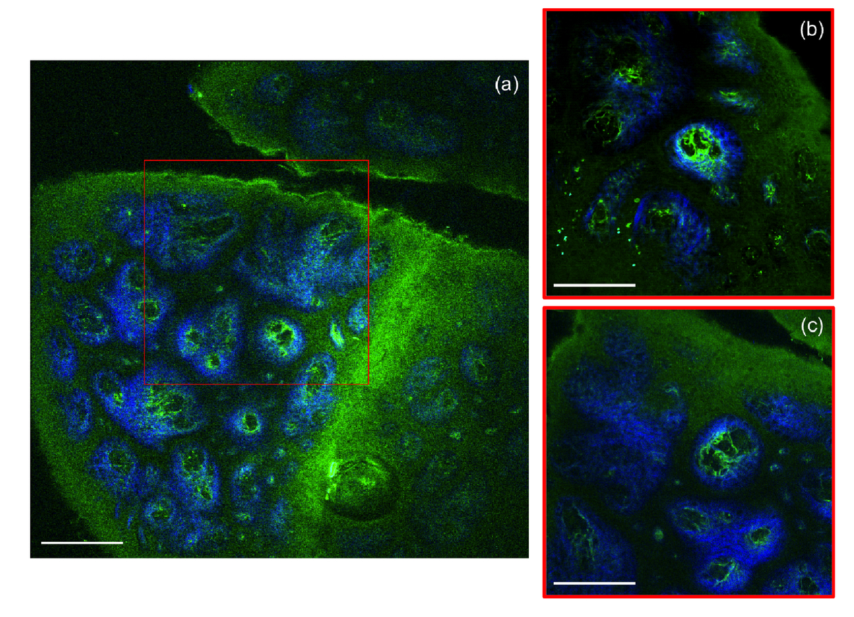 4.CONCLUSIONThe work described in this manuscript addresses two main technical challenges related to MPM skin imaging: limited field of view and slow acquisition rate of large skin areas. The MPM-based instrument proposed here is capable of imaging 0.8x0.8 mm2 skin areas at sub-micron resolution and rates that range between 0.4 to 1.6 seconds per frame (when averaging 4 to 8 frames for high SNR). This represents a 4x improvement in the FOV when compared to the images acquired with a commercial microscope using the same objective and 40x improvement in acquisition speed when compared to the available clinical MPM microscopes scanning the same FOV. Although fast scanning or wide field of view microscopes have been developed before [16, 18-21], none of these systems was optimized for nonlinear optical microscopy in the clinic. Our design is tailored specifically to maximize FOV, image speed and signal collection from key molecular components in skin tissue. The technical advancements described in this manuscript, if implemented, can significantly enhance the practical use of the nonlinear optical microscopy in clinical settings. ReferencesE. Dimitrow, M. Ziemer, M. J. Koehler et al.,
“Sensitivity and Specificity of Multiphoton Laser Tomography for In Vivo and Ex Vivo Diagnosis of Malignant Melanoma,”
Journal of Investigative Dermatology, 129
(7), 1752
–1758
(2009). https://doi.org/10.1038/jid.2008.439 Google Scholar
M. Ulrich, M. Klemp, M. E. Darvin,
“In vivo detection of basal cell carcinoma: comparison of a reflectance confocal microscope and a multiphoton tomograph,”
J Biomed Opt, 18
(6), 61229
(2013). https://doi.org/10.1117/1.JBO.18.6.061229 Google Scholar
M. Balu, K. M. Kelly, C. B. Zachary,
“Distinguishing between benign and malignant melanocytic nevi by in vivo multiphoton microscopy,”
Cancer Res, 74
(10), 2688
–97
(2014). https://doi.org/10.1158/0008-5472.CAN-13-2582 Google Scholar
M. Balu, C. B. Zachary, R. M. Harris,
“In Vivo Multiphoton Microscopy of Basal Cell Carcinoma,”
JAMA Dermatol, 151
(10), 1068
–74
(2015). https://doi.org/10.1001/jamadermatol.2015.0453 Google Scholar
M. Balu, A. Mazhar, C. K. Hayakawa,
“In vivo multiphoton NADH fluorescence reveals depth-dependent keratinocyte metabolism in human skin,”
Biophysical journal, 104
(1), 258
–67
(2013). https://doi.org/10.1016/j.bpj.2012.11.3809 Google Scholar
M. J. Koehler, K. Konig, P. Elsner,
“In vivo assessment of human skin aging by multiphoton laser scanning tomography,”
Opt Lett, 31
(19), 2879
–81
(2006). https://doi.org/10.1364/OL.31.002879 Google Scholar
Y. H. Liao, W. C. Kuo, S. Y. Chou,
“Quantitative analysis of intrinsic skin aging in dermal papillae by in vivo harmonic generation microscopy,”
Biomed Opt Express, 5
(9), 3266
–79
(2014). https://doi.org/10.1364/BOE.5.003266 Google Scholar
Y. Dancik, A. Favre, C. J. Loy,
“Use of multiphoton tomography and fluorescence lifetime imaging to investigate skin pigmentation in vivo,”
Journal of Biomedical Optics, 18
(2),
(2013). Google Scholar
T. B. Krasieva, C. Stringari, F. Liu,
“Two-photon excited fluorescence lifetime imaging and spectroscopy of melanins in vitro and in vivo,”
Journal of Biomedical Optics, 18
(3), 031107
(2013). https://doi.org/10.1117/1.JBO.18.3.031107 Google Scholar
R. B. Saager, M. Balu, V. Crosignani,
“In vivo measurements of cutaneous melanin across spatial scales: using multiphoton microscopy and spatial frequency domain spectroscopy,”
J Biomed Opt, 20
(6), 066005
(2015). https://doi.org/10.1117/1.JBO.20.6.066005 Google Scholar
R. Bazin, F. Flament, A. Colonna,
“Clinical study on the effects of a cosmetic product on dermal extracellular matrix components using a high-resolution multiphoton tomograph,”
Skin Res Technol, 16
(3), 305
–10
(2010). Google Scholar
J. Lademann, M. C. Meinke, S. Schanzer,
“In vivo methods for the analysis of the penetration of topically applied substances in and through the skin barrier,”
International Journal of Cosmetic Science, 34
(6), 551
–559
(2012). https://doi.org/10.1111/ics.2012.34.issue-6 Google Scholar
V. R. Leite-Silva, M. Le Lamer, W. Y. Sanchez,
“The effect of formulation on the penetration of coated and uncoated zinc oxide nanoparticles into the viable epidermis of human skin in vivo,”
European Journal of Pharmaceutics and Biopharmaceutics, 84
(2), 297
–308
(2013). https://doi.org/10.1016/j.ejpb.2013.01.020 Google Scholar
M. J. Koehler, M. Speicher, S. Lange-Asschenfeldt,
“Clinical application of multiphoton tomography in combination with confocal laser scanning microscopy for in vivo evaluation of skin diseases,”
Exp Dermatol, 20
(7), 589
–94
(2011). https://doi.org/10.1111/exd.2011.20.issue-7 Google Scholar
T. Meyer, M. Baumgartl, T. Gottschall,
“A compact microscope setup for multimodal nonlinear imaging in clinics and its application to disease diagnostics,”
Analyst, 138
(14), 4048
–57
(2013). https://doi.org/10.1039/c3an00354j Google Scholar
P. S. Tsai, C. Mateo, J. J. Field,
“Ultra-large field-of-view two-photon microscopy,”
Opt Express, 23
(11), 13833
–47
(2015). https://doi.org/10.1364/OE.23.013833 Google Scholar
A. Negrean, and H. D. Mansvelder,
“Optimal lens design and use in laser-scanning microscopy,”
Biomedical Optics Express, 5
(5), 1588
–1609
(2014). https://doi.org/10.1364/BOE.5.001588 Google Scholar
G. Y. Fan, H. Fujisaki, A. Miyawaki,
“Video-rate scanning two-photon excitation fluorescence microscopy and ratio imaging with cameleons,”
Biophys J, 76
(5), 2412
–20
(1999). https://doi.org/10.1016/S0006-3495(99)77396-0 Google Scholar
A. M. Lee, H. Wang, Y. Yu,
“In vivo video rate multiphoton microscopy imaging of human skin,”
Opt Lett, 36
(15), 2865
–7
(2011). https://doi.org/10.1364/OL.36.002865 Google Scholar
N. D. Kirkpatrick, E. Chung, D. C. Cook,
“Video-rate resonant scanning multiphoton microscopy: An emerging technique for intravital imaging of the tumor microenvironment,”
Intravital, 1
(1), 2012). https://doi.org/10.4161/intv.21557 Google Scholar
I. Veilleux, J. A. Spencer, D. P. Biss,
“In vivo cell tracking with video rate multimodality laser scanning microscopy,”
Ieee Journal of Selected Topics in Quantum Electronics, 14
(1), 10
–18
(2008). https://doi.org/10.1109/JSTQE.2007.912751 Google Scholar
P. S. Tsai, N. Nishimura, E. J. Yoder,
“[Principles, design and construction of a two photon scanning microscope for in vitro and in vivo brain imaging],”
CRC Press, 6
(2002). Google Scholar
J. N. Stirman, and S. L. Smith, [Mesoscale two-photon microscopy: engineering a wide field of view with cellular resolution], Society for Neuroscience, Washington, DC
(2014). Google Scholar
|