

|
|
1.INTRODUCTIONLegged robot locomotion is an active research problem and in the recent decades many research laboratories have developed prototypes — from quadrupeds operating outdoors (such as the Boston Dynamics BigDog) to experimental running bipedal robots. The motivation for humanoid robots, specifically, is the simple observation that such a form factor is useful in enabling robots to use human-centric infrastructure and tools — in particular in areas which are inaccessable to wheeled or tracked robots. This paper describes ongoing work at the University of Edinburgh’s Humanoid Robotics Project. University of Edinburgh have formed a collaboration with the United States’ National Aeronautics and Space Administration (NASA) around their R5 humanoid robot commonly known as Valkyrie. Also involved are MIT, Northeastern University and the Florida Institute for Human and Machine Cognition (IHMC) as part of NASA’s Space Robotics Challenge. We will outline the design and development of our humanoid state estimation algorithms and well as progress towards highly reliable LIDAR localization. Many of algorithms and tools discussed here were initially developed for the Boston Dynamics (BDI) Atlas during the DARPA Robotics Challenge (DRC) before being redesigned or improved for the NASA Valkyrie. 2.OVERVIEW OF NASA VALKYRIE AND COMPARISON TO BDI ATLASThe NASA Valkyrie is one of the most advanced humanoid robots in the world. The original robot was developed by NASA-JSC in 2013 during the DRC. It weighs 125 kg and stands 1.8m tall. The robot’s primary joints are controlled by electric motors and has a joint configuration similar to previous robots: namely 6 Degree-of-Freedom (DOF legs, 7 DOF arms, 3 DOF back as well as an actuated neck and fingers. As our focus here is primarily on the algorithms below presents, we direct the interested reader to the full system overview of the presented in.1 Aside from the obvious difference in actuation source (hydraulics versus electric motors with series elastic actuators) there are many simularities between Valkyrie and the Boston Dynamics Atlas. Both contain 6 degree of freedom legs, with a primary inertial measurement unit located at the pelvis link and with a force-torque sensor in each ankle. More comparative details are presented in Figure 1. Figure 1.The algorithm described in this paper have been extensively tested with both the Boston Dynamics Atlas and NASA Valkyrie humanoid robots.  Table 1.Sensor and Actuation Comparison between the Boston Dynamics Atlas (all models) and the NASA Valkyrie.
3.CONTROLControl of a humanoid robot is one of the most complex yet well explored domains of robotics research. It is out of the scope of this work to overview the control strategies used on Valkyrie in depth. In brief, the Valkyrie robot is currently controlled by momentum-based control algorithm described in.2 The approach uses convex optimization to calculate the control output of the robot given constraints regarding interfaction forces (between the ground and the robot’s feet), torque limitations and walking pattern trajectories. The approach was originally developed for the Atlas robot before being adapted to the Valkyrie in 2014. 4.STATE ESTIMATIONIn this section we describe the EKF state estimation algorithm developed for the BDI Atlas and now adapted for Valkyire. 4.1Signal preprocessingSome preprocessing is required to obtain useful measurement data. For Valkyrie, the angle of each leg joint is sensed by measuring the travel of its hydraulic actuator with an LVDT, and then computing a transformation through the joint linkage. This mapping does not account for flexion of the joint linkage when loaded or backlash when a joint changes direction. To account for these effects, we preprocess the joint angle measurements using the correction model, previously introduced by Koolen et al.2 The model assumes linear compliance at the joint level, where For Valkyrie similar preprocessing carried out, with different correction terms which are a function of the mass properties of the robot. 4.2Process modelThe state of the floating base of the robot is described by where bωb ∈ ℝ3 and bvb ∈ ℝ3 are the angular and linear velocities, wRb is the floating-base rotation matrix, and wpb = [px,py,pz]T is the base position. The angular and linear velocities are expressed in the base (pelvis) frame b, while the position and orientation of the pelvis are expressed in a fixed world frame w (as indicated by the leading superscripts above). As the IMU provides accurate measurements of the angular velocity bωb, we use the measured values directly and do not incorporate bωb in the EKF state. In addition to the floating-base state, the EKF also estimates gyro and acceleration biases, denoted bω and ba respectively. This leads us to define the global state of the EKF as the tuple The fact that the rotation matrix wRb is an overparameterization of orientation leads to constraints on the global state that cannot be handled in a standard EKF setting. To overcome this problem, we maintain orientation uncertainty in terms of a perturbation rotation in body frame represented by a minimal set of coordinates. Omitting superscripts and subscripts and summarizing,3 the true orientation of the floating base is represented by the rotation matrix R. The estimated orientation, R̂, is related to it through where χ ∈ ℝ3 is the rotation error in exponential coordinates relative to the body frame and R(χ) = eχ̂ is the corresponding perturbation rotation matrix. Here, ·̂ denotes the skew-symmetric matrix such that ·̂ x = · × x for any x ∈ ℝ3, so that eχ̂ is the rotation matrix corresponding to a rotation of |χ| about the axis defined by χ. Table 2.Contribution of various sensors to the filtered state estimate. Modes of integration found to be useful are marked ✓ and those not used here (for a variety of reasons) are indicated ✘. 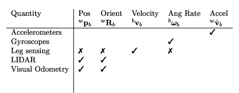 4.2.1InputsSimilar to angular velocity, the acceleration bab is measured accurately by the IMU. We treat both bωb and bab as inputs to the process model rather than measurements in the EKF - a common approach. Hence, the input vector for the EKF can be written as Following the linearization derivations from,3 Euler integration is used to produce the a priori state and covariance. 4.3Leg Kinematic Measurement modelAs with many floating base state estimation algorithms,4,5 our approach to using the leg kinematics assumes that the robot’s stance foot maintains stationary contact with the ground during part of the gait. This allows instantaneous velocity and position measurements of the robot’s floating base to be inferred via forward kinematics. Given the accuracy of the IMU orientation sensors, we choose to use joint sensing to measure only the position and velocity of the pelvis. Of course, perfectly clean and stable ground contact is seldom achieved in practice. However, we assert that for short periods (on the order of the sample time of our sensors) these assumptions are reasonable. An estimate w p̂b [k] of the position of the floating base at time step k can be computed using the current floating base orientation estimate in the world frame, wRb [k], and the previous estimated position of the stationary foot, wpf [k - 1], where wpb/f [k] denotes the position of the floating base with respect to the foot, which can be computed using the filtered leg joint positions and the floating base orientation estimate, wθb [k]. Two types of filter measurement could be formulated using this position estimate. The simplest approach would be to directly apply (6) as a position measurement within the EKF. However, because of the inaccuracy in joint sensing and because the robot’s foot does not always remain motionless after initial contact, we use the difference between consecutive position estimates over a short period of time to create a velocity measurement of the pelvis frame, where h = 3 msec is the time step duration. This approach is more attractive because each resultant observation is a separate measurement of the robot’s velocity and does not accumulate a history of, for example, the effects of non-ideal ground contact or the footplate rolling or sliding. The influence of an erroneous velocity is transient and quickly corrected by subsequent observations. Using both measurement types together has been explored in related work,6 but we avoid doing so as it raises the possibility of creating inconsistencies, particularly when combined with position measurements derived from the LIDAR module (presented in the following section). To use the leg kinematics for state estimation, it is necessary to determine which of the feet is most likely to be in stationary contact with the ground. We use a Schmitt trigger with a threshold of 575 N to classify contact forces sensed by the robot’s 3-axis foot force-torque sensors and detect whether either foot is in contact. A simple state machine then decides which foot is most reliably in contact and thus will provide the basis for kinematic measurements. The output of the foot contact classifier is demonstrated in the upper plot in Figure 2. Figure 2.Left: Evolution of foot force signals for the left (green) and right (red) foot during two steps. Lower plots show raw velocity, filter output, ground truth and error relative to VICON. Right: Localization accuracy for a variety of walking experiments. Position drift on left scale (in meters), yaw drift on right (in degrees). Error (versus ground truth) of the BDI state estimator (blue), our kinematic-only EKF (green), and LIDAR (red) estimators are shown.  Figure 3.For LIDAR localization, the robot first collects a static point cloud of its environment which is used for subsequent localization. In our experiments we could localize the robot walking backward and forward over the illustrated walking course even though the robot had no rear facing sensors.  In the specific case of walking up stairs, the controller needs to use the toe of the trailing foot to push the robot forward and upward while the foot is not in stationary contact. While the design of the state estimator is almost entirely independent of the walking controller, as we increased the speed of locomotion we needed to feedback the active contact points from the controller to the state estimator in this situation. We also classify other events in the gait cycle. Striking contact is determined when a force of 20-30N is maintained for more than 5msec. Breaking contact is determined when force falls below 275N. Because these impacts create unrealistic measurements, the EKF integrates these measurements with higher measurement covariance. We note that when the robot is in a double support stance, information from both legs could be leveraged to provide additional kinematic measurements. For simplicity we currently neglect this information. Figure 2 contains a number of plots comparing (1) the raw pelvis velocity measurements inferred from kinematics with (2) the output of our integrating filter and (3) the velocity estimated from VICON motion capture. Using only raw leg position signals, the typical pelvis velocity standard deviation measured while standing stationary was 7.6 cm/sec. Adding joint-level filters reduced this to 2.3 cm/sec. Integrating filtered leg joint position into the EKF further reduced the error standard deviation to 1.4 cm/sec. Finally, as mentioned in Section 4.3 the revolute joints states are filtered separately. The compliance model mentioned above is again used in preprocessing, before extended Kalman Filtering. 4.4Yaw Bias Measurement ModelAn additional challenge when developing a system for autonomy is Yaw Bias drift. The IMU gyroscopes contain bias resulting in an inability to directly measure rotation drift without directly sensing it. To detect this bias we introducted a detector which used occasional observations of the robot being stationary to capture the orientation and to infer that all subsequent rotation is dur to the rotation bias. By slowly evolving this estimate, an accurate and stable rotation bias can be directly estimated and removed. However, inherently this bias is much lower for the Atlas robot (with a tactical grade IMU) versus the MEMS IMU on the Valkyrie robot. We estimate that the former drifts at a rate 10 times less than the MEMS IMU. 5.STATE ESTIMATION EVALUATIONWe evaluate performance in a variety of experiments. In the following our localization estimate system sequentially updated a set of desired footstep locations that were individually passed to the BDI controller during locomotion. Figure 2 summarizes the results of a substantial set of experiments for a variety of walking patterns totaling 57 minutes of operation and 155 meters traveled. We are currently capable of walking approximately 13 times faster (0.40 m/s vs 0.03 m/s) with 30 cm longer steps (70 cm) compared with the quasi-static walking controller provided with the robot while maintaining equal or better footstep placement precision. At this speed the double-support time per step is roughly 0.1 sec and the gait is fully dynamic (the COM is outside of the support polygon). Although this is still a slow gait by human standards, we point out that our primary development goal to this point has been to achieve accurate and robust walking control in environments related to the DRC (cinder blocks, ramps, gaps, etc.) and we have not yet invested considerable effort improving the speed and efficiency of the robot’s walking motions. For traversing ramps and cinder blocks, raising the heel of the trailing foot while walking improves kinematic reachability. The controller actively monitors the knee angle and breaks heel contact when the trailing leg is nearly fully extended, resulting in a heel-raising behavior. In our implementation, the controller and state estimator are separate processes that independently estimate foot contacts (the controller uses both sensed and desired contact information to classify a foot as in contact). We therefore had to tune the contact classifier in the estimator to handle the slightly different contact behaviors encountered in flat ground, steps, and ramps. A variety of experiments to test both the controller and the state estimator are described in7 including climbing narrow stairs with partial foot contacts, traversing irregular terrain and applying pushes to imbalance the robot. 6.DRIFT SUPPRESSION WITH LIDARWhile the drift of the combined inertial and kinematic estimator is capable of achieving relatively low drift, it remains unsuitable for accurate walking over tens of meters. We aim to use our exteroceptive sensors to remain localized with the robot’s environment. In particular, we use LIDAR to continuously infer the robot’s position relative to a prior map while walking. 6.1Gaussian Particle FilterWe first adapted the approach originally proposed by Bry et al.3 using a Gaussian Particle Filter (GPF), which was presented in.8 In typical operation, the robot is first commanded to stand still for about 30 seconds while it collects a full 3D point cloud of its environment (see Figure 4). This cloud is then converted into a probabilistic occupancy grid (OctoMap)9 against which efficient localization comparisons later performed during locomotion. While the MAV experiments presented in3 required offline mapping with a separate sensor, our legged humanoid and actuated LIDAR with 30 m range permit the map to be constructed immediately prior to operation and immediately utilized while walking. Furthermore, if the robot were to approach the map boundary, on-line construction of a new map could easily be performed during operation. Figure 4.Left: Initially the point clouds are analysed to remove clutter. Right: Subsequently the resultant point clouds are aligned to a single reference cloud. This results in objects in the scene, such as a valve, being consistent across each observation. These results are from data collected in the DRC Finals by the MIT team.  Since the LIDAR is fundamentally a planar 2D sensor, only a subset of the state vector (namely x, y and yaw in the rotating sensor plane) is observable at any given instant. We therefore partition the full state vector into observable and unobservable sub-states, and use a GPF to incorporate each laser measurement over the observable variables. The particle filter samples are weighted according to the proposed sub-state likelihood, which is computed by comparing the LIDAR measurements, projected from the sub-state, to the prior map. From these weighted samples a mean and covariance, and in turn an equivalent Kalman measurement update for the full state vector are calculated resulting in a correction to the base position and yaw. Given the competition environment of the DARPA Robotics Challenge and our inability to test in precisely the DRC conditions (outdoors with a large crowd of moving people), we typically operated without the LIDAR localization module because:
In Section 6.2 we discuss our future plans to improve this important module. 6.2ICP-based LocalizationSo as to improve performance in dynamics situations our most recent approach uses Iterative Closest Point (ICP) to retain localization, with a number of significant modificaitons. We analyze the effect of overlap variations on registration performance and demonstrate that where overlap varies, outlier filtering needs to be tuned accordingly. We define a novel parameter which gives a measure of this overlap. In this context, we propose a strategy for robust non-incremental registration. The pre-filtering module selects planar macro-features from the input clouds, discarding clutter. Outlier filtering is automatically tuned at run-time to allow registration to a common reference in conditions of non-uniform overlap. In Figure 4 initial results are presented. 7.CONCLUSIONIn this work we have present recent work on state estimation and LIDAR localization developed as part of the University of Edinburgh - NASA collaboration using the Valkyrie humanoid. Other ongoing working includes dense visual mapping, collision free motion planning and model based control. ACKNOWLEDGMENTSThe research presented here is the result of research carried out the Edinburgh Humanoid Robotics Team which is comprised of members of several research groups within the School of Informatics at University of Edinburgh. Interested readers are directed to the following address for further details A number of the software modules mentioned here have open sourced and are described there. REFERENCESRadford, N. A., Strawser, P., Hambuchen, K., Mehling, J. S., Verdeyen, W. K., Donnan, A. S., Holley, J., Sanchez, J., Nguyen, V., Bridgwater, L., Berka, R., Ambrose, R., Myles Markee, M., Fraser-Chanpong, N. J., McQuin, C., Yamokoski, J. D., Hart, S., Guo, R., Parsons, A., Wightman, B., Dinh, P., Ames, B., Blakely, C., Edmondson, C., Sommers, B., Rea, R., Bibby, H., Howard, B., Niu, L., Lee, A., Conover, M., Truong, L., Reed, R., Chesney, D., Platt, R., Johnson, G., Fok, C.-L., Paine, N., Sentis, L., Cousineau, E., Sinnet, R., Lack, J., Powell, M., Morris, B., Ames, A., and Akinyode, J.,,
“Valkyrie: NASA’s first bipedal humanoid robot,”
J. of Field Robotics, 32
(3), 397
–419
(2015). https://doi.org/10.1002/rob.21560 Google Scholar
Koolen, T., Bertrand, S., Thomas, G., de Boer, T., Wu, T., Smith, J., Englsberger, J., and Pratt, J.,,
“Design of a momentum-based control framework and application to the humanoid robot atlas,”
Intl. J. of Humanoid Robotics, 13
(2016). Google Scholar
Bry, A., Bachrach, A., and Roy, N.,,
“State estimation for aggressive flight in GPS-denied environments using onboard sensing,”
IEEE Intl. Conf. on Robotics and Automation (ICRA), 1
–8
(2012). Google Scholar
Stephens, B. J.,,
“State estimation for force-controlled humanoid balance using simple models in the presence of modeling error,”
IEEE Intl. Conf. on Robotics and Automation (ICRA), 3994
–3999
(2011). https://doi.org/10.1109/ICRA.2011.5980358 Google Scholar
Bloesch, M., Hutter, M., Hoepflinger, M. A., Leutenegger, S., Gehring, C., Remy, C. D., and Siegwart, R.,,
“State estimation for legged robots - consistent fusion of leg kinematics and IMU,”
Robotics: Science and Systems (RSS),
(2012). Google Scholar
Xinjilefu, X., Feng, S., Huang, W., and Atkeson, C.,,
“Decoupled state estimation for humanoids using full-body dynamics,”
IEEE Intl. Conf. on Robotics and Automation (ICRA),
(2014). Google Scholar
Kuindersma, S., Deits, R., Fallon, M. F., Valenzuela, A., Dai, H., Permenter, F., Koolen, T., Marion, P., and Tedrake, R.,,
“Optimization-based locomotion planning, estimation, and control design for atlas,”
Autonomous Robots, 40 429
–455
(2016). https://doi.org/10.1007/s10514-015-9479-3 Google Scholar
Fallon, M. F., Antone, M., Roy, N., and Teller, S.,,
“Drift-free humanoid state estimation fusing kinematic, inertial and LIDAR sensing,”
EEE/RSJ Int. Conf. on Humanoid Robots,
(2014). Google Scholar
Wurm, K. M., Hornung, A., Bennewitz, M., Stachniss, C., and Burgard, W.,,
“OctoMap: A probabilistic, flexible, and compact 3D map representation for robotic systems,”
Proc. of the ICRA 2010 Workshop on Best Practice in 3D Perception and Modeling for Mobile Manipulation,
(2010). Google Scholar
|


