

|
|
1.INTRODUCTIONAt Sandia National Laboratories, the Z Pulsed Power Facility (also referred to as the Z-Accelerator, Z-Machine, or simply Z), as seen in Fig. 1, is the flagship research facility in the area of radiation effects and high energy density (HED) science.1 Energy stored in capacitors is rapidly discharged through a series of pulse forming lines and guided to a load in the vacuum center section of Z. In this process, the delivered electrical pulse at Z can have up to 22 MJ of energy in a duration of 100 to 300 ns, yielding peak electrical powers of 80 TW. At the load, the resulting high current from such a discharge generates enough magnetic field that the Lorentz force rapidly accelerates matter for the selected HED experiment. In the specific case of Z-pinches, the accelerated matter cyclindrically pinches on the central Z axis to form a hot dense plasma that is a significant x-ray source, producing up to 2.7 MJ and 350 TW of x-rays. With this in mind, Z has many applications in HED science, including Inertial Confinement Fusion (ICF)2 and Magnetized Liner Inertial Fusion (MagLIF),3-5 Dynamic Material Properties (DMP) and Equation of State (EOS) studies,6 Z astrophysical plasma properties,7 and radiation effects sciences. Figure 1.The Z-Accelerator Hi-Bay. The accelerator has structure on concentric rings, with the outer most having an outer diameter of 33 m. The center section, shown in the inset, is a 3.2 m diameter vacuum section where the HED science occurs. The blue vacuum tube and overlaid green arrow indicate the path of the Z-Backlighter laser beam.  Due to the conditions and densities generated, diagnostics are challenging. Fortunately, x-ray flash radiography (commonly referred to as backlighting) provides a wealth of information about these HED events. The Z-Backlighter Laser Facility uses focused high energy lasers on appropriate targets to generate plasma-based x-ray sources for this purpose. Such x-ray sources can also be used for x-ray Thomson scattering studies or for x-ray diffraction on dynamically compressed materials.6 In addition, once a high energy laser is available, it can be used beyond diagnostics-only applications. In this context, Z-Backlighter lasers can be used to pre-heat fuel in MagLIF studies. A discussion of these applications will follow a summary of the Z-Backlighter Facility, from its core lasers systems to its collateral efforts of the Target Bay and the Optics Support Facility. 2.THE Z-BACKLIGHTER LASER FACILITYThe Z-Backlighter Laser Facility is comprised of three high energy lasers: the Z-Beamlet Laser, the Z-Petawatt Laser, and the Chaco Laser, which are summarized Table 1. These systems run from the 10's of Joules up to several kiloJoules, with pulse durations from sub-picosecond up to several nanoseconds. The higher energy systems are based on Nd:Phosphate glass operating at 1054 nm and its second harmonic at 527nm. The smaller Chaco system is based on Nd:YAG and Nd:Silicate glass operating at 1064 nm and 532 nm. Before discussing each of these systems in more detail, it is worth discussing the operational footprint of the facility. As seen in Fig. 2, the bulk of the facilty is about 20,000 ft2 (1,800 m2 ) in area. Most of this is broken into two Class-100,000 Hi-Bay spaces with a ceiling height of 20 ft (6.1m) that are accessible by crane. One of the Hi-Bays is referred to as the Laser Bay (because it houses the bulk of the laser sources) while the other is referred to as the Target Bay (because it houses the bulk of the target chambers used for applications and development work in support of the Z-Accelerator). To be clear, there is some juxtaposition that occurs with a 200 TW target chamber being in the Laser Bay and with the Chaco Laser being in the Target Bay. This area measurement does not include various mezzanine spaces associated with the split level working environment or the offices and tangential storage that support operations. Figure 2.A bird's eye view of the Z-Accelerator and the Z-backlighter Facility. The Z-backlighter is made up of about 20,000 ft2 (1,800 m2) of space from the Optics Support Facility (OSF), the Laser Bay, the Target Bay, and the Capacitor Rooms (used to drive the flashlamps that pump the main Z-Beamlet and Z-Petawatt slab amplifiers). For scale, a human is shown just below the Target Bay.  2.1The Z-Beamlet LaserThe Z-Beamlet Laser (ZBL) is a re-application of the Beamlet Laser, which operated from 1992-1998 as the single-beamline prototype of the National Igntion Facility at Lawrence Livermore National Laboratories.8 This Nd:Phosphate glass laser was re-located to Sandia National Laboratories beginning in 1998 to support Z experi-ments.9 Warehouse space at Sandia that was near to the Z-Accelerator was renovated into Class-100,000 Hi-Bay space in order to provide a clean operating environment for the laser that would mitigate laser damage from particulate contaminants. By March of 2001, the first system shots were fired into a small target chamber, with beam delivery to Z demonstrating radiographs of dynamic Z events by June of 2001. The system architecture, shown in Fig. 3, is essentially the same as in its Beamlet era. In this sense, a seed source at the nanoJoule level is amplified in three succesively larger multipass amplifiers to the multi-kiloJoule level. As a seed source, a continuous wave (CW) Yb fiber laser source is amplified and temporally chopped and shaped into nanoJoule-level, nanosecond-scale pulses at 250 Hz (with this frequency being locked to a centralized Rb clock). Using a fast electical pulser to drive an electro-optic modulator (EOM) for this pulseshaping, initial backlighting efforts started with 0.3 ns full-width-at-half-maximum (FWHM) pulsewidths in order to show minimal motional blurring of dynamically moving Z targets over the pulse duration. To increase the laser energy and hence the x-ray flux (for better signal-to-noise images) while still showing minimal evidence of motional blurring, the decision was quickly made to increase this duration to 1 ns. Subsequently, using multiple electrical pulses to a single EOM, low level pre-pulses were added 1 to 2 ns earlier than the main pulse in order to further increase x-ray flux based on an increase in conversion efficiency from the pre-pulse.10,11 More recently, an arbitrary waveform generator (AWG) drives the EOM, creating completely adjustable pulseshapes from the seed laser within a temporal window from 0.3 to 10 ns, although limitations further down the laser chain currently set the upper pulsewidth window at 5 ns. The use of the AWG not only allows more pre-pulse control within the available temporal window but also allows detailed shaping of the main pulse in order to compensate gain saturation pulse-shape distortion effects from subsequent amplifiers.8 One should note that, until recently, pulsewidths beyond 2 ns were not only radiographically undesirable but also unallowable due to concerns of damage and losses by transverse Stimulated Brillouin Scatter (SBS). As the laser mission space has changed to desire more energy, longer pulses were needed. To address this, a phase modulation system and failsafe has been added to the laser to prevent transverse SBS risk, allowing the pulswidths to increase to cover the full 5 ns window and to subsequently increase the output energy.12-14 Figure 3.Z-Beamlet Laser (ZBL). (Left) Schematic. (Upper right) Photo of the ZBL System. (Lower Right) Engineering view of the vacuum Final Optics Assembly (FOA).  After the critical seed laser, the pulse is transported via fiber to the ring regenerative amplifier. The ring regenerative amplifier design uses a Pockels cell to lock the pulse into the ring cavity for about 20 round trips. On each trip, the pulse sees gain from two 6 mm diameter Nd:Phosphate glass rods running at 0.2 Hz (to avoid thermal lensing effects). Output pulses of a few mJ energy are then gated by an exit “slicer” Pockels cell in order to eliminate the undesired roundtrip leakage pre-pulses from the regenerative amplifier. The beam is then expanded and the beam profile is re-shaped from a round Gaussian into a square super-Gaussian (“flattop”) via a birefringent beamshaper and apodizer. The apodizer serves as the object plane for subsequent relay imaging throughout the laser amplifier chain. The apodized beam is then injected into the 4-pass Nd:Phosphate glass rod amplifier (50mm diameter), which can boost the energy to several Joules with a single shot rate of 15 minutes. After this, the beam magnifies in the vacuum cavity spital filter and enters the final multipass main slab amplifier, with a beamsize of 31 cm × 31 cm. Using a plasma electrode Pockels cell (PEPC) to lock the pulse into the cavity, the pulse circulates through the 11 Nd:Phosphate glass amplifier slabs four times, boosting the energy up to a maximum of 6 kJ at 1054 nm. Each pass though the cavity is relay imaged via the cavity spatial filter, with each pass using a different pinhole at the focal plane to avoid pinhole closure effects.15,16 As set by thermal loading of the flashlamp-pumped slab amplifiers, the shot rate of at least 3 hours yields about 3 shots per day maximum with normal staffing. The amplified pulse is further relayed via the vacuum transport spatial filter to a large frequency doubling crystal (currently 37cm × 37cm × 2cm Type I KDP), where conversion to 527nm light occurs with up to 75% efficiency for up to 4.5 kJ of energy. This is one of the unique aspects of ZBL with respect to other ICF lasers, which often opt for third harmonic target interactions. In our case, second harmonic minimizes target back-reflection risks, improves target coupling for x-ray generation compared to the fundamental wavelength, and minimizes operational concerns of ultraviolet light absorption/transmission and associated optical damage that could occur with third harmonic light. After frequency doubling, the beam is then relayed through another vacuum transport telescope to the Z-Accelerator for usage, although the beam can be deflected into the Target Bay for use in a number of stand-alone target chambers (see Section 3.2). At either location, focal intensities can reach up to 1017 W/cm2. As this intensity is ample for the type of x-rays generated in the 1 to 9 keV range (see Section 4), a unique multi-frame backlighting (MFB) option has been implemented17,18 which amplitude splits the beam into two halves at a standard polarizer prior to the main amplifiers, creates an adjustable delay from 2 to 20 ns, and then recombines the beams in the near field with a slight angular and focal separation prior to injection into the slab amplifier. This necessitates 2 nested sets of the required 4 pinhole array for each pulse, with one set having additional focal plane staggering due to the input focal shift. The angular separation of the beams is designed to be in the non-critical axis of the frequency doubling crystal (i.e. the one not required for phase matching) such that efficient doubling occurs for each pulse. When focused in Z, the angular and focal separation creates two distinct focal spots, allowing two different target foils to be used. As such, the multiframe option allows time-delayed capture of a single rapid Z event with two frames (using traditional temporally integrated detectors on each) at potentially different x-ray wavelengths.18-20 2.2The Z-Petawatt LaserWhile the Z-Beamlet Laser can generate x-rays effectively up to 9keV, the conversion efficiency from laser energy to x-rays drops quickly at higher x-ray energies. 21-23 One path to obtain higher photon energy x-rays is to utilize a higher peak power laser, such as the petawatt-class systems around the world. 24,25 To this end, Sandia constructed the Z-Petawatt laser, a chirped pulse amplification laser system using Nd:Phosphate glass as the gain medium26'27 (see Fig. 4). The system uses a Ti:Sapphire mode-locked oscillator tuned to 1054nm. The cavity has been adjusted to run at 80 MHz, which (using piezo-driven cavity mirrors and “lock to clock” methods) is an easy frequency to synchronize with the centralized facility Rb clock standard. The output is temporally stretched to about 3 ns (with a chirp of 4 nm/ns) before it becomes the seed in a 3-stage optical parametric chirped pulse amplifier (OPCPA) system. This OPCPA system produces 50 mJ pulses at 10 Hz with about 9 nm of bandwidth. The pulse is then apodized into a round super-Gaussian beam which is relay imaged via vacuum spatial filters through successfively larger double-pass Nd:Phosphate glass rod amplifiers of 16 mm, 25 mm, 45 mm, and 64 mm diameter. This beam can reach more than 10 J in a single-shot mode, depending upon which amplifiers are active. The injection lens and cavity vacuum spatial filter set the beamsize to 15 cm, at which point the beam double-passes 10 of the ZBL-style Nd:Phosphate glass amplifier slabs. The slabs are only double-passed due to the lack of a PEPC on the ZPW system originally as well as insufficient space to incorporate the longer spatial filter required for a four-pass design like ZBL. The beamsize is also undersized or sub-apertured for the main slab amplifiers, which was a decision made due to space constraints, optic costs, and grating availability issues when the system was constructed. We should point out that the sub-aperture beamsize minimizes prompt aberrations from the main slab amplifiers, which are more prominent near the slab edges. However, the rod amplifiers produce a prompt aberration which corresponds to focus due to their geometry. Due to the reproducible nature of this prompt focus, it can be corrected via a single actuator adaptive optic designed at Sandia.28 Figure 4.Z-Petawatt Laser (ZPW). (Left) Schematic. (Upper right) Photo of the ZPW System. (Lower Right) Interior of 200 TW Compressor with 21cm x 60 cm MLD gratings.  At this sub-aperture beamsize, 425 J has been demonstrated to date. The amplified beam at this point can go one of two directions. At near maximum energy, the beam can be expanded 3x in diameter and go to a larger aperture petawatt compressor using 94 cm 1480 line/mm gold gratings. Conversely, at a reduced energy of 100 J in 500 fs (or up to 200 J in the >10ps range), the beam can go at its existing size to a sub-aperture 200 TW grating compressor utilizing 21 cm × 60 cm 1740 line/mm multi-layer dielectric (MLD) gratings. This compressed beam can be routed to diagnostics and a 1.5 m spherical local target chamber using an f/4 off-axis parabola in the Laser Bay. Typical diagnostics there include: Thomson parabola, optical probe beam, singlephoton counting CCD, bent crystal x-ray spectrometers and imagers, x-ray pinhole cameras, and a femtosecond optical streak camera. Initial operations of this 200 TW chamber showed potential target back-reflection risks. This lead to a PEPC being installed at the main slab amplifier cavity exit which, in combination with an earlier polarizer, provides sufficient back-reflection protection. 2.3The Chaco LaserThe Chaco Laser is a mixed Nd:YAG and Nd:Silicate glass system with an architechture that mimics the larger systems in the facility at a slightly different wavelength. A CW, single-longitudinal mode seed laser is chopped and shaped via an AWG-driven EOM. Via fiber delivery, this pulse is injected into an ultra-stable diode-pumped Nd:YAG ring regenerative amplifier. The 10 Hz output has typically 7.5 mJ of energy per pulse with ±0.6% RMS amplitude jitter and 35 ps RMS timing jitter. A slicer Pockels cell temporally gates out any undesired pre-pulses from the regenerative amplifier. After a 6 mm diameter 10 Hz Nd:YAG booster amplifier, the beam is apodized into a round super-Gaussian beam. This plane is then relay imaged and magnified via vacuum spatial filters through successively larger aperture Nd:Silicate glass rod amplifiers: a single-pass 9 mm rod, a double-pass 16 mm rod, a single-pass 25 mm rod, a single-pass 45 mm rod, and a final single-pass 64 mm rod (see Fig. 5). The output energy depends upon the pulseshape and pulsewidth, with 15 J at 1064 nm being demonstrated at 0.3 ns and over 50 J at 6 ns. As with ZBL, frequency doubling is generally done to improve target interactions while mitigating back-reflected laser risk to the amplifiers. At 532 nm, local intensities in the Chaco target chamber can exceed 1016 W/cm2 with observed tight focusing to less than 10 μm FWHM. Figure 5.Chaco Laser. (Left) Schematic. (Upper right) Photo of the Chaco System. (Lower Right) Chaco local Target Chamber.  The Chaco system has been used to generate soft x-rays (He-like sources under 5 keV) for a variety of diagnostic development and calibration efforts. In addition, the system (like all lasers in the facility) is inherently synchronized with other lasers through the use of a facility master clock. As such, it can be used as a probe laser in the various chambers via a sub-floor probe beam delivery system (see Fig. 9). Due to the 532 nm wavelength, the Chaco Laser allows spectral discrimination from any 527 nm or 1054 nm light used for target interactions with the other lasers. Recently, the probe beam delivery system was converted to relay-imaged vacuum transport. This allows improved beam quality along with high energy capability delivered to any of the other target chambers (beyond its local one, see Section 3.2). With this capability, the roles have flipped in some recent experiments where the Chaco Laser has begun serving as a source for laser-driven shocks in materials while the other lasers provide x-ray probe capability. When used as a probe beam at low energy (without all of the amplifiers firing), the Chaco Laser has some unique multi-pulse capabilities. Within the 12.5 ns roundtrip time of the regenerative amplifier, the AWG can be used to create arbitrary pulse sequences within an 8 ns window. After the amplifier chain, beam splitting, delay, and beam recombination can allow pulses with separations from 2 ns to 20 ns. Tuned leakage of pulses each roundtrip of the regenerative amplifier can yield pulse sequences at a fixed 12.5 ns separation. Finally, with the cavity tuned to a 12.5 ns roundtrip time, the custom Pockels cell inside the regenerative amplifier can be rapidly pulsed to yield multiple pulses of 50 ns or greater separation (which remains within the 250 μs gain lifetime of the laser). These methods can be used in combination to provide larger pulse sequences, with 8 pulse sequences having been demonstrated. Such sequences can then be used with high speed framing cameras to capture high frame rate “movies”. Due to the extremely fast time scales, the framing camera used is a custom Sandia hybrid complementary metal oxide semiconductor (hCMOS) camera device29-31 capable at this point of 4 frames at 4 ns or more spacing. Using an 8 pulse sequence from the Chaco Laser and interleaving the triggering of two of these hCMOS cameras, one can generate an 8 frame movie of a single HED event at a frame separation of 2 ns or longer (see Fig. 6). Figure 6.Single-shot multi-frame shadowgraphy with the Chaco Laser. The Chaco probe beam/hCMOS camera development allows study of the laser-driven evolution of thin plastics (1mm) over a laser entrance hole (on the left side of each frame), with a 300 Torr backfill of Ne behind (on the right side). This one experiment captured eight 532 nm probe beam pulses (at 2 ns spacing) on 2 interleaved hCMOS cameras for a single ZBL shot (at 2kJ/527nm).  3.Z-BACKLIGHTER SUPPORT FACILITIES3.1The Optics Support FacilityWhen delivering the ZBL beam to Z for backlighting, the beam enters a final optics assembly (FOA) enclosure (see Fig. 3) at the top of the accelerator populated by a 90° folding mirror, an f=3.2m aspheric lens, a 3 cm thick vacuum window, and a 1 cm thick debris shield (to protect the window). The latter two items have 32.5 cm × 32.5 cm cross-section, need anti-reflection coatings on both sides, and are consumed on each Z shot. To the last point, the energetic Z-Accelerator events yield high velocity shrapnel and debris (see Fig. 7). For standard backlighting, the laser is directed off-axis with respect to the Z-pinch, which allows some extra debris protection. Some Z shots (such as MagLIF) require on-axis laser light delivered to the Z pinch, which exposes the debris shield to direct axial shrapnel and debris and subsequently more severe damage. To this end, one must consider that a catastrophic vacuum window failure could result in the rapid release of more that 5 MJ of stored vacuum energy as well as the large-scale dispersion of silica and Z target “soot” powders. This issue is eliminated via the use of a vacuum FOA, wherein there is no stored energy difference between the sides of the vacuum barrier window. Furthermore, a sealed FOA also reduces exposure from the vapors of 2 ML of transformer oil and 2.3 ML of deionized water in the Z Hi-Bay. Figure 7.Used Debris Shields. (Left) Moderate damage on Z shot consisting of several shrapnel sites and “soot” coating. (Right) Severe damage during a Z shot.  Bearing in mind that a supply chain for the coated vacuum windows and debris shields is needed (amounting to about 50 per year of each compared to about 150 total shots on the Z-Accelerator each year), Sandia quickly determined that supplies of polished substrates could be obtained reasonably but that the cost and lead time driver was really the coatings. To this end, the Z-Backlighter facility established a Class-100 cleanroom area in 2006, referred to as the Optics Support Facility (OSF), and installed a 90” coating chamber with certain associated optical metrology capabilities32 (see Fig. 8). In its standard configuration, the coating chamber can accommodate 3 rotating planets that each hold an optic as large as 94 cm in diameter. To date, the largest optic coated has been a 94 cm × 42 cm grating (103 cm diagonal) 33 using a two-planet system. The chamber uses e-beam deposition with the option of ion-assisted deposition to produce dielectric coating layers. Most optics use coatings consisting of HfO2 and SiO2 layers due to their ability to meet our optical and laser damage requirements, although other oxides such as Al2O3, TiO2, Nb2O5, Ta2O534-36 have also been investigated. Most of the coatings are for anti-reflection (AR) or high reflection (HR) at 1054 nm and 1064 nm or at the second harmonics of 527 nm and 532 nm, with specifications covering a variety of use angles and use environments (typically vacuum or dry air). To account for broadband Z-Petawatt needs and to accomodate the common facility central laser wavelengths, fundamental wavelength coatings are often specified to cover from 1045 to 1064 nm. To assess the coating performance of these, coated optics can be checked in-house via a commercial spectrophotometer, commercial 10 cm interferometers at 633 nm or at 1054 nm, and our custom large-area reflectometer. Figure 8.Optics Support Facility. (Left) Handling of a truncated 94 cm fold mirror. (Middle) Interior of the coating chamber during the coating of a truncated 94 cm fold mirror. (Right) Final product for a 75 cm HR coating (200 lb weight).  Off site, samples are routinely sent for laser damage testing at commercial vendors. Typically under 1064 nm testing at 3.5 ns pulsewidth, these results come back in the range of 17 to 25 J/cm2 for AR coatings and in the range of 75 to 85 J/cm2 for HR coatings. Such results have been corroborated at Sandia with resident small-area laser damage testing using a nanosecond scale Q-switched laser (which can test in normal or injection-seeded modes at 1064 nm and 532 nm). Similarly, laser damage testing can be performed at 0.5 ps (or longer when chirped) using a 1054 nm or 527 nm ultrashort pulse laser source from ZPW. Laser damage testing at Sandia can be in vacuum, ambient air, or under an arbitrary gas environment. 37-40 3.2The Target BayThe Z-Accelerator performs nominally 1 shot per work day (as limited by daily operational processes) while the Z-Beamlet and Z-Petawatt can fire up to 3 shots per day each (as limited by the thermal loading of the main amplifiers). The scarcity of Z shots for development and the extra capacity of lasers shots drives one to have stand-alone target capability in addition to Z in order to scope and develop new laser methods and applications. Accordingly, mirrors can be inserted in the Z-Beamlet and Z-Petawatt beamlines to route the lasers to various target chambers available in the Target Bay (see Fig. 9). Figure 9.The Z-Backlighter Target Bay. (left) A bird's eye view of the Target Bay. Most of the view looks down on the ground level. However, the ZBL and ZPW beams are initially routed to the floor target chambers from the upper level mezzanine switchyard box. Elements prior to this (such as the ZPW large vacuum grating compressor and the ZPW/ZBL relay transport tubes) are not shown. When delivered to the floor level, the lower deck of the periscope box and the two diverter boxes are used to route ZBL to any of the 4 chambers that can utilize it. By comparison, in the Target Bay, ZPW can only be routed to the central Chama chamber. (upper right) View of the central Chama chamber and the nearby vacuum transport hardware. (lower right) View of the Pecos chamber. 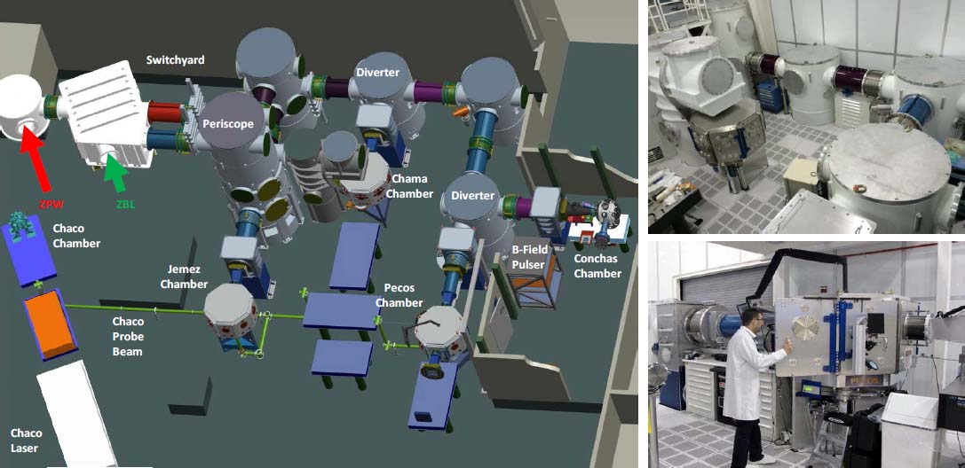 The 5 local stand-alone vacuum target chambers, named for New Mexico rivers, each have different emphasis, which allows several experimental campaigns to take place in parallel. Typical diagnostics at any of these can include any of those mentioned for the 200 TW system (see Section 2.2) as well as a custom Photonic Doppler Velocimetry (PDV)41,42 system operating at 1064nm (to be commensurate with facility laser safety protocols). The vessel descriptions, available lasers, and current experimental emphasis are as follows:
The latter chamber, Conchas, is the only one currently with access to a 30 T magnetic-field pulser for studying magnetized HED science conditions. The pulser is re-applied hardware that was built under a Sandia collaboration with the University of Texas43,44 to examine magnetized cluster fusion. The scalable system currently uses 5 capacitors capable of 100 kA each to deliver a 1 ms pulse that can generate up to 30 T at the load. 4.APPLICATIONS4.1X-Ray SourcesThe primary use of lasers within the facility is for the generation of short-duration, pulsed x-rays which can be applied to flash radiography, x-ray Thomson scatter diagnostics, or dynamic x-ray diffraction studies. To do this, the synchronized high energy laser source is focused onto a chosen target material near the dynamic object to be probed. The laser can generate x-rays from a variety of mechanisms in dense plasmas, which for our facility include:
The thermal line sources typically require a very hot plasma (kTe ~ 2keV), requiring sufficient heating time and energy, which makes them the primary source generated by the nanosecond-scale Z-Beamlet system. The “optical to x-ray” conversion efficiency for this source rolls off enough at around 9 keV, making higher photon energies unachievable21-23 (see Fig. 10). Fortunately, the conversion efficiency for Kα sources crosses that of the thermal line sources at about this point, making Kα sources the dominant line source option above 9 keV. The dislocation of the inner shell electrons by impact ionization required for this method utilizes an intense, high electric field laser, making the Z-Petawatt system the driver for the regime. It is worth noting that the pre-pulse option, which can enhance conversion efficiencies for thermal line sources (see Section 2.1), does not work for Kα sources as they require a cold target for the interaction. Finally, when referring to ZPW-generated x-ray sources, the same plasma will naturally create a certain amount of Bremsstrahlung continuum x-rays, which often causes signal-to-noise issues in detection. This can be addressed in part by reducing the intensity via temporal broadening of the laser pulse to the point where Kα lines are only slightly decreased while Bremsstrahlung continuum is significantly decreased. If desired, Bremsstrahlung x-rays can and have been used in some backlighting studies. 4.2X-Ray BacklightingInitially, backlighting images on Z were taken with ZBL using point-projection imaging, wherein the x-rays from the laser plasma went through the Z radiograph object and were recorded on film or image plate. As the resolution depended on x-ray spotsize (which is typically in the 100 to 200μm FWHM range for ZBL), the images tended to be of poor detail. The geometry of the approach also lead to small field of views along with potential direct exposure of the film to Z object x-rays and debris. At the x-ray wavlength used, the latter issue necessitated a fast electromagnetic shutter to protect the image detector.45 For better quality images, researchers began to use bent crystal imaging.46,47 By matching the lattice structure of a bent crystalline x-ray optic to the x-ray line emission wavelength, a reflective x-ray imaging system with high spatial resolution ( <20 μm) and large field of view was available. Furthermore, the spectral selectivity of the crystal reduced image plane exposure from broadband x-rays from the Z object along the backlighter x-ray path. The geometry also allows line-of-sight shielding from direct Z object x-rays and debris, eliminating the need for the electromagnetic shutter. For these reasons, bent crystal imaging has become the x-ray imaging option of choice at the Z facility. Bent crystal imagers have now been fielded at 1.8 keV (Si target), 6.2keV (Mn target), and 7.2keV (Co target) on Z while imagers at 7.8keV (Ni target), 8.1 keV (Cu target), and 15.7 keV (Zr target) have been demonstrated in stand-alone laser target chamber work. Recent work has rigorously matched crystal choices of various cuts to the appropriate x-ray line sources in order to tabulate a master list of bent crystal imaging options. 48 4.3MagLIF ExperimentsMagnetized Liner Inertial Fusion (MagLIF) is a rapidly developing area of research at Sandia. Essentially, a liner cylinder is filled with the desired deuterium (or deuterium-tritium gas in the future), which is sealed at the top and bottom of the liner. The standard azimuthal field begins the implosion process. At early times, an additional axial magnetic field is applied. During this early time, a kiloJoule-level beam from Z-Beamlet enters the top of the compressing pinch via the thin top laser entrance hole (LEH) to pre-heat the fusion fuel. The axial magnetic field, which confines the resulting alpha particle products and improves heating, is compressed during the process. The net result shows improved fusion yields at lower pressures and densities than with non-magnetized ICF. The process of laser coupling is one of the more tricky parts to the process. For example, nonlinear backscatter effects at the thin LEH can deterioriate the laser energy deposition in the gas fuel. A prepulse a few nanoseconds prior to the main pulse can be used to diffuse the material to the point that the density is sufficiently low for good fuel coupling. This issue drives interest in parametric studies involving prepulses, which such studies being restricted currently to a 5 ns temporal window for Z-Beamlet due to laser architechture limitations. Similarly, the nonlinear backscatter effects are driven by the laser intensity at the LEH, more specifically by beam profile intensity inhomogeneities (i.e., “hot spots”). This is driving studies with continuous phase plates to improve beam uniformity. Assuming the coupling can be improved, MagLIF scaling underscores the need for more pre-heat laser energy. 5.THE FUTUREThe facility is constantly evolving to meet new needs, although a common theme is “more energy”. For the Z-Beamlet system to meet this goal, longer pulsewidths are needed to extract the energy efficiently, requiring modifications to the existing cavity and transport spatial filter pinholes to address pinhole closure issues. Furthermore, additional amplifiers are needed, with these being placed in the booster location just after the main amplifiers. Under the primary backlighting mission, these booster amplifiers have not been needed due to shorter pulsewidth B-integral limitations but the MagLIF effort can utilize longer pulsewidths, allowing higher energy capability. Such new amplifiers require additional pulsed power and associated space. This becomes a challenge but it can be addressed via other infrastructure modifications. The Z-Petawatt system is currently in the midst of an upgrade to increase the small sub-aperture beam to a full-aperture ZBL beamsize. When coupled with larger 94 cm x 42 cm MLD gratings,33 this will increase the available short-pulse laser energy for target interactions. In addition to larger optics apart from the amplifiers themselves, the full-aperture upgrade requires a longer vacuum cavity spatial filter, which requires a shorter amplifier length to fit in the spatial constraints of our building. To solve this, we will utilize the fact that the main Nd:Phosphate glass slab amplifier units have a 2 × 1 configuration, where the entire unit is pumped by the flashlamps but only the top is normally populated with laser glass while the bottom is populated by a “dummy” absorbing glass. 14 By populating the bottom aperture with laser glass and wrapping the beam around to the bottom, we can save the space we need and transition from a single-aperture 10 amplifier unit design to a folded double-aperture 5 amplifier unit design. Both have 10 Nd:Phosphate glass slabs but the latter uses half of the spatial length and half of the pulsed power. As a result, we can use the excess 5 amplifier units and pulsed power for the ZBL booster amplifier project. The Z-Petawatt system is currently in the midst of another nested upgrade to allow nanosecond-scale, narrow-bandwidth light to be amplified, frequency-doubled, and co-propagated with ZBL (see Fig. 4) via a dichroic beam combiner.49 The process, currently referred to as co-injection, yields a fully adjustable delay 527 nm pulse that can be pointed at the same target as ZBL, allowing either an adjustable pre-pulse or additional energy for the MagLIF process. When the pointing is shifted away from ZBL's focus, new backlighting opportunities can be explored. 6.CONCLUSIONThe Z-Backlighter facility began operations in 2001 and has continued to expand with new capabilities and systems through the years. The facility now incorporates three high energy lasers and a variety of support infrastructure, including the Optics Support Facility and the Target Bay. New infrastructure and capabilities will be added in the near future to address changing technical objectives. 7.ACKNOWLEDGMENTSWe would like to acknowledge other Sandia colleagues, specifically Jeff W. Kellogg, Daniel I. Headley, Quinn Looker, Jeff Georgeson, and Drew Johnson (as well as members of the Z Pulsed Power Facility), for their valued support through the years. Sandia is a multi-mission laboratory operated by Sandia Corporation, a Lockheed Martin Company, for the United States Department of Energy's National Nuclear Security Administration under contract DE-AC04-4AL85000. REFERENCESM.K. Matzen, M.A. Sweeney, R.G. Adams, J.R. Asay, J.E. Bailey, G.R. Bennett, D.E. Bliss, D.D. Bloomquist, T.A. Brunner, R.B. Campbell, G.A. Chandler, C.A. Coverdale, M.E. Cuneo, J.P. Davis, cDeeney, M.P. Desjarlais, G.L. Donovan, C.J. Garasi, T.A. Haill, C.A. Hall, D.L. Hanson, M.J. Hurst, B. Jones, M.D. Knudson, R.J. Leeper, R.W. Lemke, M.G. Mazarakis, D.H. McDaniel, T.A. Mehlhorn, T.J. Nash, C.L. Olson, J.L. Porter, P.K. Rambo, S.E. Rosenthal, G.A. Rochau, L.E. Ruggles, C.L. Ruiz, T.W.L. Sanford, J.F. Seamen, D.B. Sinars, S.A. Slutz, I.C. Smith, K.W. Struve, W.A. Stygar, R.A. Vesey, E.A. Weinbrecht, D.F. Wenger, and E.P. Yu,
“Pulsed-power-driven high energy density physics and inertial confinement fusion research,”
Physics of Plasmas, 12
(5), 055503
(2005). https://doi.org/10.1063/1.1891746 Google Scholar
M.E. Cuneo, R.A. Vesey, G.R. Bennett, D.B. Sinars, W.A. Stygar, E.M. Waisman, J.L. Porter, P.K. Rambo, I.C. Smith, S.V. Lebedev, J.P. Chittenden, D.E. Bliss, T.J. Nash, G.A. Chandler, B.B. Afeyan, E.P. Yu, R.B. Campbell, R.G. Adams, D.L. Hanson, T.A. Mehlhorn, and M.K. Matzen,
“Progress in symmetric icf capsule implosions and wire-array Z-pinch source physics for double-pinch-driven hohlraums,”
Plasma Physics and Controlled Fusion, 48
(2),
(2006). https://doi.org/10.1088/0741-3335/48/2/R01 Google Scholar
S.A. Slutz, M.C. Herrmann, R.A. Vesey, A.B. Sefkow, D.B. Sinars, D.C. Rovang, K.J. Peterson, and M.E. Cuneo,
“Pulsed-power-driven cylindrical liner implosions of laser preheated fuel magnetized with an axial field,”
Physics of Plasmas, 17
(5), 056303-1
–056303-15
(2010). https://doi.org/10.1063/1.3333505 Google Scholar
M.E. Cuneo, M.C. Herrmann, D.B. Sinars, S.A. Slutz, W.A. Stygar, R.A. Vesey, A.B. Sefkow, G.A. Rochau, G.A. Chandler, J.E. Bailey, J.L. Porter, R.D. McBride, D.C. Rovang, M.G. Mazarakis, E.P. Yu, D.C. Lamppa, K.J. Peterson, C. Nakhleh, S.B. Hansen, A.J. Lopez, M.E. Savage, C.A. Jennings, M.R. Martin, R.W. Lemke, B.W. Atherton, I.C. Smith, P.K. Rambo, M. Jones, M.R. Lopez, P.J. Christenson, M.A. Sweeney, B. Jones, L.A. McPherson, E. Harding, M.R. Gomez, P.F. Knapp, T.J. Awe, R.J. Leeper, C.L. Ruiz, G.W. Cooper, K.D. Hahn, J. McKenney, A.C. Owen, G.R. McKee, G. T. Leifeste, D. J. Ampleford, E. M. Waisman, A. Harvey-Thompson, R.J. Kaye, M.H. Hess, S.E. Rosenthal, and M.K. Matzen,
“Magnetically driven implosions for inertial confinement fusion at Sandia National Laboratories,”
Plasma Science, IEEE Transactions on, 40
(12), 3222
–3245
(2012). https://doi.org/10.1109/TPS.2012.2223488 Google Scholar
A.B. Sefkow, S.A. Slutz, J.M. Koning, M.M. Marinak, K.J. Peterson, D.B. Sinars, and R. A. Vesey,
“Design of magnetized liner inertial fusion experiments using the Z Facility),”
Physics of Plasmas, 21
(7), 072711
(2014). https://doi.org/10.1063/1.4890298 Google Scholar
T. Ao, E.C. Harding, J.E. Bailey, R.W. Lemke, M.P. Desjarlais, S.B. Hansen, I.C. Smith, M. Geissel, A. Maurer, J. Reneker, D. Romero, D.B. Sinars, G.A. Rochau, and J.F. Benage,
“Demonstration of space-resolved x-ray Thomson scattering capability for warm dense matter experiments on the Z accelerator,”
High Energy Density Physics, 18 26
–37
(2016). https://doi.org/10.1016/j.hedp.2016.01.002 Google Scholar
G.A. Rochau, J.E. Bailey, R.E. Falcon, G.P. Loisel, T. Nagayama, R.C. Mancini, I. Hall, D.E. Winget, M.H. Montgomery, and D.A. Liedahl,
“ZAPP: The Z Astrophysical Plasma Properties collaboration,”
Physics of Plasmas, 21
(5), 056308
(2014). https://doi.org/10.1063/1.4875330 Google Scholar
B.M. VanWonterghem, J.R. Murray, J.H. Campbell, D.R. Speck, C.E. Barker, I.C. Smith, D.F. Browning, and W.C. Behrendt,
“Performance of a prototype for a large-aperture multipass Nd:Glass laser for inertial confinement fusion,”
Applied Optics, 36
(21), 4932
–53
(1997). https://doi.org/10.1364/AO.36.004932 Google Scholar
P.K. Rambo, I.C. Smith, J.L. Porter, M.J. Hurst, C.S. Speas, R.G. Adams, A.J. Garcia, E. Dawson, B.D. Thurston, C. Wakefield, J.W. Kellogg, M.J. Slattery, H.C. Ives, R.S. Broyles, J.A. Caird, A.C. Erlandson, J.E. Murray, W.C. Behrendt, N.D. Neilsen, and J.M. Narduzzi,
“Z-Beamlet: A multikilojoule, terawatt-class laser system,”
Applied Optics, 44
(12), 2421
–2430
(2005). https://doi.org/10.1364/AO.44.002421 Google Scholar
D.B. Sinars, G.R. Bennett, M.C. Herrmann, I.C. Smith, C.S. Speas, L.E. Ruggles, and J.L. Porter,
“Enhancement of x-ray yield from the Z-Beamlet laser for monochromatic backlighting by using a prepulse,”
Review of Scientific Instruments, 10E309
(2006). https://doi.org/10.1063/1.2228515 Google Scholar
D. Babonneau, M. Primout, F. Girard, J.-P. Jadaud, M. Naudy, B. Villette, S. Depierreux, C. Blancard, G. Faussurier, K.B. Fournier, L. Suter, R. Kauffman, S. Glenzer, M.C. Miller, J. Grn, and J. Davis,
“Efficient multi-kev x-ray sources from laser-exploded metallic thin foils,”
Physics ofPlasmas, 15
(9), 092702
(2008). https://doi.org/10.1063/1.2973480 Google Scholar
P.K. Rambo, D.J. Armstrong, J. Schwarz, I.C. Smith, J. Shores, C.S. Speas, and J.L. Porter, Injection of a phase modulated source into the Z-Beamlet laser for increased energy extraction,
(2014). https://doi.org/10.2172/1164594 Google Scholar
D.J. Armstrong,
“Operators manual and technical reference for the Z-Beamlet phase modulation failsafe system: Version 1,”
SAND Report, 78
(2014). Google Scholar
J. Schwarz, P. Rambo, D. Armstrong, M. Schollmeier, I. Smith, J. Shores, M. Geissel, M. Kimmel, and J. Porter,
“Recent laser upgrades at Sandias Z-Backlighter facility in order to accommodate new requirements for magnetic liner inertial fusion on the Z-machine,”
High Power Laser Science and Engineering,
(2016). https://doi.org/10.1017/hpl.2016.30 Google Scholar
J.M. Auerbach, N.C. Holmes, J.T. Hunt, and G.J. Linford,
“Closure phenomena in pinholes irradiated by Nd laser pulses,”
Applied Optics, 18
(14), 2495
–2499
(1979). https://doi.org/10.1364/AO.18.002495 Google Scholar
J.E. Murray, D. Milam, C.D. Boley, K.G. Estabrook, and J.A. Caird,
“Spatial filter pinhole development for the National Ignition Facility,”
Applied Optics, 39
(9), 1405
–1420
(2000). https://doi.org/10.1364/AO.39.001405 Google Scholar
J.A. Caird, A.C. Erlandson, W.A. Molander, J.E. Murray, G.K. Robertson, I.C. Smith, D.B. Sinars, and J.L. Porter,
“Z-Beamlet (ZBL) Multi-Frame Back-lighter (MFB) system for ICF/plasma diagnostics,”
J. Phys. IV France, 133 943
–949
(2006). https://doi.org/10.1051/jp4:2006133190 Google Scholar
G.R. Bennett, I.C. Smith, J.E. Shores, D.B. Sinars, G. Robertson, B.W. Atherton, M.C. Jones, and J.L. Porter,
“220ns interframe time 2-frame 6.151kev x-ray imaging on the recently upgraded Z accelerator: A progress report,”
Review of Scientific Instruments, 79
(10), 10E914
(2008). https://doi.org/10.1063/1.2956823 Google Scholar
M.R. Martin, R.W. Lemke, R.D. McBride, J.P. Davis, D.H. Dolan, M.D. Knudson, K.R. Cochrane, D.B. Sinars, I.C. Smith, M. Savage, W.A. Stygar, K. Killebrew, D.G. Flicker, and M.C. Herrmann,
“Solid liner implosions on Z for producing multi-megabar, shockless compressions,”
Physics of Plasmas, 19
(5), 056310
(2012). https://doi.org/10.1063/1.3694519 Google Scholar
R.D. McBride, M.R. Martin, R.W. Lemke, J.B. Greenly, C.A. Jennings, D.C. Rovang, D.B. Sinars, M.E. Cuneo, M.C. Herrmann, S.A. Slutz, C.W. Nakhleh, D.D. Ryutov, J.-P. Davis, D.G. Flicker, B.E. Blue, K. Tomlinson, D. Schroen, R.M. Stamm, G.E. Smith, J.K. Moore, T.J. Rogers, G.K. Robertson, R.J. Kamm, I.C. Smith, M. Savage, W.A. Stygar, G.A. Rochau, M. Jones, M.R. Lopez, J.L. Porter, and M.K. Matzen,
“Beryllium liner implosion experiments on the Z accelerator in preparation for magnetized liner inertial fusion,”
Physics ofPlasmas, 20
(5), 056309
(2013). https://doi.org/10.1063/1.4803079 Google Scholar
L.E. Ruggles, J.L. Porter, P.K. Rambo, W.W. Simpson, M.F. Vargas, G.R. Bennett, and I.C. Smith,
“Measurements of 4-10 kev x-ray production with the Z-Beamlet laser,”
Rev. of Scientific Instruments, 74
(3), 2206
–2210
(2003). https://doi.org/10.1063/1.1537854 Google Scholar
M.A. Barrios, K.B. Fournier, S.P. Regan, O. Landen, M. May, Y.P. Opachich, K. Widmann, D.K. Bradley, and G.W. Collins,
“Backlighter development at the National Ignition Facility (NIF): Zinc to Zirconium,”
High Energy Density Physics, 9
(3), 626
–634
(2013). https://doi.org/10.1016/j.hedp.2013.05.018 Google Scholar
H.-S. Park, B.R. Maddox, E. Giraldez, S.P. Hatchett, L.T. Hudson, N. Izumi, M.H. Key, S. Le Pape, A.J. MacKinnon, A.G. MacPhee, P.K. Patel, T.W. Phillips, B.A. Remington, J.F. Seely, R. Tommasini, R. Town, J. Workman, and E. Brambrink,
“High-resolution 17-75kev backlighters for high energy density experiments,”
Physics ofPlasmas, 15
(7), 072705
(2008). https://doi.org/10.1063/1.2957918 Google Scholar
J.D. Zuegel, S. Borneis, C. Barty, B. Legarrec, C. Danson, N. Miyanaga, P.K. Rambo, C. Leblanc, T.J. Kessler, A.W. Schmid, L.J. Waxer, J.H. Kelly, B. Kruschwitz, R. Jungquist, E. Moses, J. Britten, I. Jo-vanovic, J. Dawson, and N. Blanchot,
“Laser challenges for fast ignition,”
Fusion Science and Technology, 49
(3), 453
–482
(2006). https://doi.org/10.13182/FST06-A1161 Google Scholar
C. Danson, D. Hillier, N. Hopps, and D. Neely,
“Petawatt class lasers worldwide,”
High Power Laser Science and Engineering, 3 1
–14
(2015). https://doi.org/10.1017/hpl.2014.52 Google Scholar
J. Schwarz, P. Rambo, M. Geissel, M. Kimmel, E. Brambrink, B. Atherton, and J. Glassman,
“A hybrid OPCPA/Nd:Phosphate glass multi-terawatt laser system for seeding of a petawatt laser,”
Optics Communications, 281
(19), 4984
–92
(2008). https://doi.org/10.1016/j.optcom.2008.06.043 Google Scholar
J. Schwarz, P. Rambo, M. Geissel, A. Edens, I. Smith, E. Brambrink, M. Kimmel, and B. Atherton,
“Activation of the Z-petawatt laser at Sandia National Laboratories,”
in Journal of Physics: Conference Series,
032020
–4
(2008). Google Scholar
J. Schwarz, M. Geissel, P. Rambo, J. Porter, D. Headley, and M. Ramsey,
“Development of a variable focal length concave mirror for on-shot thermal lens correction in rod amplifiers,”
Optics Express, 14
(23), 10957
–10969
(2006). https://doi.org/10.1364/OE.14.010957 Google Scholar
L. Claus, L. Fang, R. Kay, M. Kimmel, J. Long, G. Robertson, M. Sanchez, J. Stahoviak, D. Trotter, and J.L. Porter,
“An overview of the ultrafast x-ray imager (UXI) program at Sandia Labs,”
in Proc. SPIE,
1
–12
(2015). Google Scholar
H. Chen, N. Palmer, M. Dayton, A. Carpenter, M.B. Schneider, P.M. Bell, D.K. Bradley, L.D. Claus, L. Fang, T. Hilsabeck, M. Hohenberger, O.S. Jones, J.D. Kilkenny, M.W. Kimmel, G. Robertson, G. Rochau, M.O. Sanchez, J.W. Stahoviak, D.C. Trotter, and J.L. Porter,
“A high-speed two-frame, 1-2 ns gated x-ray CMOS imager used as a hohlraum diagnostic on the National Ignition Facility (invited),”
Review of Scientific Instruments, 87
(11), 11E203
(2016). https://doi.org/10.1063/1.4962252 Google Scholar
L. Claus, G. Robertson, L. Fang, R. Kay, M.W. Kimmel, M. Sanchez, J.W. Stahoviak, D. Trotter, and J.L. Porter,
“Initial characterization results of a 1024x448 25-m multi-frame camera with 2ns integration time for the ultrafast x-ray imager (UXI) program at Sandia National Laboratories,”
in Proc. SPIE,
1
–11
(2016). Google Scholar
J. Bellum, D. Kletecka, P. Rambo, I. Smith, M. Kimmel, J. Schwarz, M. Geissel, G. Copeland, B. Atherton, D. Smith, C. Smith, and C. Khripin,
“Meeting thin film design and production challenges for laser damage resistant optical coatings at the Sandia large optics coating operation,”
in Proc. SPIE,
1
–13
(2009). Google Scholar
J. Schwarz, P. Rambo, M. Geissel, M. Kimmel, M. Schollmeier, I. Smith, J. Bellum, D. Kletecka, A. Sefkow, D. Smith, and B. Atherton,
“Z-Backlighter facility upgrades: a path to short/long pulse, multi-frame, multi-color x-ray backlighting at the Z-accelerator,”
in Proc. SPIE,
1
–14
(2011). Google Scholar
J. Bellum, E. Field, D. Kletecka, and F. Long,
“Reactive ion-assisted deposition of e-beam evaporated titanium for high refractive index TiO2 layers and laser damage resistant, broad bandwidth, high-reflection coatings,”
Applied Optics, 53
(4), A205
–A211
(2014). https://doi.org/10.1364/AO.53.00A205 Google Scholar
E. Field, J.C. Bellum, and D, E. Kletecka,
“Laser damage comparisons of broad-bandwidth, high-reflection optical coatings containing TiO2, Nb2O5, or Ta2O5 high-index layers,”
Optical Engineering, 56
(1), 011018
(2016). https://doi.org/10.1117/1.OE.56.1.011018 Google Scholar
J. Bellum, T. Winstone, L. Lamaignere, M. Sozet, M. Kimmel, P. Rambo, E. Field, and D. Kletecka,
“Analysis of laser damage tests on coatings designed for broad bandwidth high reflection of femtosecond pulses,”
Optical Engineering, 56
(1), 011012
(2016). https://doi.org/10.1117/1.OE.56.1.011012 Google Scholar
J. Schwarz, L.E. Ruggles, P. Rambo, and J.L. Porter,
“Highly sensitive method for measuring the onset of damage using a micro channel plate,”
in Proc. SPIE,
379
–384
(2005). Google Scholar
M. Kimmel, J. Schwarz, P. Rambo, M. Geissel, and B. Atherton,
“Short pulse laser damage testing on nitrocellulose and polyimide thin films in vacuum with application to laser debris shields,”
in Proc. SPIE,
1
–9
(2008). Google Scholar
M. Kimmel, P. Rambo, R. Broyles, M. Geissel, J. Schwarz, J. Bellum, and B. Atherton,
“Optical damage testing at the Z-Backlighter facility at Sandia National Laboratories,”
in Proc. SPIE,
1
–8
(2009). Google Scholar
M. Kimmel, P. Rambo, J. Schwarz, J.C. Bellum, and B. Atherton,
“Dual wavelength laser damage testing for high energy lasers,”
in Proc. SPIE,
1
–7
(2010). Google Scholar
T.Ao and D.H. Dolan, PhotonÀc Doppler Velocimetry Measurements of Materials Under Dynamic Compression, 411
–412 Springer, New York, New York, NY
(2011). Google Scholar
D.H. Dolan, R.W. Lemke, R.D. McBride, M.R. Martin, E. Harding, D.G. Dalton, B.E. Blue, and S.S. Walker,
“Tracking an imploding cylinder with photonic doppler velocimetry,”
Review of Scientific Instruments, 84
(5), 055102
(2013). https://doi.org/10.1063/1.4803074 Google Scholar
K. Struve, J. Argo, R. Bengtson, D. Headley, J. Kellogg, S. Lewis, H. Quevedo, M. Savage, B. Stoltzfus, C. Waugh, and M. Wisher,
“Status of the 2 MA driver for creating 2 MG magnetic fields for cluster fusion experiments,”
in 2011 IEEE Pulsed Power Conference,
580
–585
(2011). Google Scholar
M. Wisher, W. Bang, R.D. Bengtson, S.M. Lewis, M. McCormick, H.J. Quevedo, and K.W. Struve,
“The design and performance of a portable megagauss magnetic field generator for laser/cluster interactions,”
in Magnetic Field Generation and Related Topics (MEGAGUSS), 2012 14th International Conference on Megagauss,
1
–7
(2012). Google Scholar
D.C. Rovang, W.W. Simpson, L.E. Ruggles, and J.L. Porter,
“An electromagnetic fast shutter system for debris mitigation on Z,”
Pulsed Power Plasma Science, 2001. PPPS-2001. Digest of Technical Papers, 2 1012
–1015
(2001). https://doi.org/10.1109/PPPS.2001.1001714 Google Scholar
D.B. Sinars, M.E. Cuneo, G.R. Bennett, D.F. Wenger, L.E. Ruggles, M.F. Vargas, J.L. Porter, R.G. Adams, D. W. Johnson, K.L. Keller, P.K. Rambo, D.C. Rovang, H. Seamen, W.W. Simpson, I.C. Smith, and S.C. Speas,
“Monochromatic x-ray backlighting of wire-array Z-pinch plasmas using spherically bent quartz crystals,”
Review of Scientific Instruments, 74
(3), 2202
–2205
(2003). https://doi.org/10.1063/1.1537853 Google Scholar
M.S. Schollmeier, M. Geissel, J.E. Shores, I.C. Smith, and J.L. Porter,
“Performance of bent-crystal x-ray microscopes for high energy density physics research,”
Applied Optics, 54
(16), 5147
–5161
(2015). https://doi.org/10.1364/AO.54.005147 Google Scholar
M. Schollmeier,
“Systematic Search for Spherical Crystal X-ray Microscopes Matching 1-25 keV Spectral Line Sources,”
Review of Scientific Instruments,
(2016). https://doi.org/10.1063/1.4972248 Google Scholar
J.C. Bellum, E.S. Field, D.E. Kletecka, P.K. Rambo, and I.C. Smith,
“Design and laser damage properties of a dichroic beam combiner coating for 22.5-deg incidence and s polarization with high transmission at 527nm and high reflection at 1054nm,”
Optical Engineering, 56
(1), 011020
(2016). https://doi.org/10.1117/1.OE.56.1.011020 Google Scholar
|


