|
|
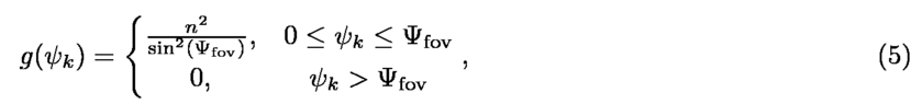
1.INTRODUCTIONOver the past decade, the exponentially growing demand for mobile wireless traffic has motived a number of new technologies for the next generation 5G wireless architecture in order to provide wireless services with higher data rates, lower latency and significantly improved quality of service (QoS). Among them, light-fidelity (LiFi)1-5 exploits the unlicensed visible light spectrum (in the vicinity of 430 - 770 THz) for bidirectional, high-speed and fully networked wireless communication. Compared to antenna-based radio frequency (RF) technologies, LiFi typically uses existing light-emitting diodes (LEDs) as the signal transmitter, which therefore is more cost-effective and energy-efficient. Experimental works have demonstrated 5 Gb/s data rate by using a single Gallium Nitride μLED with a maximum optical power of around 3 mW.6 Due to existing design and fabrication process, the 3 dB bandwidth of LEDs typically ranges from 10 to 60 MHz. For even higher data rates, laser diodes (LDs) can be used as a promising alternative, and from our recent experimental results it is anticipated that over 100 Gb/s data rate can be achieved under standard indoor illumination levels.7 Visible light communication (VLC), as a point-to-point communication technique, uses intensity modulation and direct detection (IM/DD)8 to transmit data. LiFi differs from VLC in that it stands for a complete wireless networking system including bidirectional communication, multiuser access, user mobility support, handover, etc. Based on the fact that there is a widespread deployment of LED lighting in homes, offices and streetlights, LiFi can be added to existing heterogeneous networks as an additional network layer. The benefit of this is that LiFi can greatly improves the overall network capacity since it receives zero interference from, and adds zero interference to its RF counterparts. Also, since light does not pass through opaque objects, LiFi inherently offers higher information security than RF systems. Earlier works have studied an indoor VLC network integrated with power line communication (PLC). Limited by the achievable data rate of the power lines, only 1 Mb/s data rate was reported.9 Given that there are a large number of LEDs installed in an indoor environment, the capacity of a typical LiFi network is expected to exceed hundreds of Gb/s. In this case, optical fibres become a suitable option to be installed as the backbone of high-speed LiFi networks. Fig. 1 gives the schematic diagram of a simplified LiFi network integrated with fibre communication. The infrastructure consists of a central office (CO), which is connected to a metro network and a number of LiFi access points (APs) via optical fibre links. Power cables are connected between a power supply and LiFi APs to provide electricity but not for information transmission. Between APs and mobile users are the LiFi link, through which both downlink and uplink communication are conducted, wirelessly. Therefore, LiFi transforms high-speed fibre links into wireless ones. Compared to metal wires, optical fibres offer a higher signal bandwidth and are able to transmit signals with lower losses. More importantly, optical fibres transmit only light signals, not electricity. Therefore, they are immune to electromagnetic interference, which is a problem that metal wires suffer excessively. Now since LiFi links are used for data communication between LEDs and mobile users, inter-user interference becomes an imminent problem that needs to be addressed in order to fully exploit the capacity of LiFi networks. Traditional methods are based on interference avoidance, such as time/frequency division multiple access (T/FDMA), in which multiuser interference is alleviated by dividing the totally available communication resources among users. However, these methods lead to inefficient use of the already-scarce wireless resources. A user-centric cluster formation technique employing vectored transmission (VT) was proposed in10 for efficient interference mitigation in LiFi networks. In this paper, we focus on exploiting the multiuser interference to improve the overall achievable rate of LiFi networks. Our solutions are based on non-orthogonal multiple access (NOMA) with successive interference cancellation (SIC) approach.11’12 The rest of the paper is organized as follows. In Sec. 2, a multiuser downlink system model is introduced. SIC with imperfect interference cancellation is studied in Sec. 3, in which the equivalent signal-to-interference-plus-noise ratio (SINR) is compared between NOMA and OMA. Simulation results are provided in Sec. 4 and conclusions are drawn in Sec. 5. 2.SYSTEM MODEL2.1DCO-OFDMMultiple variants of optical orthogonal frequency division multiplexing (OFDM) have been proposed for LiFi.13 Direct current optical OFDM (DCO-OFDM) is assumed here as the modulation technique, in which signals are transmitted in parallel on a number of orthogonal subcarriers with different central frequencies. Without loss of generality, it is assumed that there are K bit streams to be transmitted to K users. A simplified block diagram illustrating the principle of NOMA is shown in Fig. 2. First, input bit streams for each user are framed and mapped to complex symbols, Xk(l), where k =1, …, K, based on the selected modulation schemes, e.g. quadrature amplitude modulation (QAM). Here l is the index of the subcarrier. For each OFDM frame, the number of subcarriers used to carry information is equal to NPPT/2 — 1, where NPPT is the size of inverse fast Fourier transform (IFFT) and FFT. This spectral efficiency loss is caused by the Hermitian symmetry constraint For a large number of subcarriers, xk (t) tends to follow a Gaussian distribution, with zero mean and variance where iDC is the DC bias added to the LED in order to ensure a positive instantaneous intensity. The output of Eq. (2) is given by: A cyclic prefix (CP) of length NCP — 1 is then inserted at the start of each OFDM frame. This CP is composed of the last NCP — 1 symbols of each frame: The cyclic prefix is required to be larger than the maximum delay spread of the channel Td in order for the receiver to avoid inter-symbol interference (ISI), since the channel dispersion affects only the first NCP — 1 symbols. With the insertion of CP. the spectral efficiency of DCO-OFDM is given by: where M is the constellation size of the QAM symbol used. It is easy to show that x(t) in Eq. (2) also follows the Gaussian distribution with mean value iDC and variance 2.2LiFi ChannelFor downlink transmission, where the LiFi AP of interest is placed at the origin and K users are uniformly distributed underneath within a circular area of radius re. The vertical distance between the LiFi AP and users is denoted by L. The AP is assumed to be facing vertically downward and the users are assumed to be facing vertically upward with a field-of-view (FOV) of Ψfov. The LiFi channel can be characterized by its dominant line-of-sight (LOS) path, whose propagation gain is given by:14 where m = —1/log2(cos(Φ1/2)) is the Lambertian order of the LED and Φ1/2 denotes its semi-angle; A denotes the detection area of the PD and Rp denotes its responsivity; dk is the Euclidean distance between the LED and the user; Φk is the angle of irradiance; ψk is the angle of incidence; T(ψk) represents the gain of the optical filter used at the receiver; and represents the gain of the optical concentrator, given by:14 where n is the reflective index of the optical concentrator used at the receiver front-end. After propagating through free space, the received signal at the k-th user can be expressed as: where nk (t) is the real-valued Gaussian noise with zero mean and single-sided variance N0. 3.SUCCESSIVE INTERFERENCE CANCELLATIONBefore detecting its own signal, SIC is performed at each user to remove the signals that are intended for other users with lower channel gains. Since the signal intended for user 1 has the highest power, the SIC process begins by detecting and canceling signal x1(t) at each user. As a result, the SINR of user k during its first SIC process is given by: If γk(1) is greater than a threshold b, it is assumed that the receiver is able to detect and subtract this signal from the received aggregate signal before the next SIC process. However, in the SIC process, it requires the receiver to reconstruct the waveform of the decoded users. Since this operation involves channel estimation as well as signal decoding, that can never be perfect in practice, there exist interference cancellation errors. Therefore, residual interference exists in the remaining part of the signal, and this unavoidably degrades the performance of the next SIC process. Such imperfect interference cancellation process can be characterized with a proportional model, 15 in which it is assumed that the cancellation of a signal with power P can only cancel a portion of the signal and leaves a residual interference power of zP, with z ≤ 1. Given that the first SIC process at user k is successful, the SINR for the second SIC process is: Again, the second SIC process is successful if γk (2) > b, and unsuccessful otherwise. Given that the (s — 1)-th SIC process is successful, the SINR of the s-th SIC is: where s = 2, …, k — 1, k + 1, …, K. The SIC process repeats by increasing the value of s until γk (s) ≤ b. At the end of SIC process, the SINR for user k is finally given by: where K denotes the set which includes all of the users and Sk denotes the set including users whose signals have be detected and canceled by user k during the SIC process, i.e. γk(Sk) > b. An iterative algorithm to find Sk is described in Algorithm 1, in which In OMA, signals for different users are transmitted using orthogonal resources so that the interference term does not exist. The SINR, which is equivalent to signal-to-noise ratio (SNR) in this case, is given by: To allow a fair comparison between OMA and NOMA, we define an equivalent SINR for the OMA case. The equivalent SINR, denoted by The equivalent SINR can be solved as: Note that in OMA the equivalent SINR is equal to the actual SINR in the single user scenario, i.e. K = 1. As the number of users increases, the equivalent SINR drops exponentially, which therefore limits the total capacity of the network. These results are also shown in Fig. 3. For example, assuming a LiFi network with 8 users, the equivalent SINR is around 0 dB when the actual SINR is 25 dB. Table 1:Simulation parameters
4.SIMULATION RESULTSIn this section, Monte Carlo simulations are conducted to evaluate the performance of NOMA in a multiuser LiFi network. The performance metrics under investigation are the cumulative distribution function (CDF) of the equivalent SINR and the achieved bit error rate (BER) using DCO-OFDM at each user. The parameters used for the simulation setup are summarized in Table. 1, if not otherwise specified. 4.1CDF of the Equivalent SINRBy assuming uniformly distributed mobile users, the empirical CDF of the equivalent SINR for both NOMA and OMA are obtained from a total number of 10, 000 realizations, as shown in Fig. 4. An exponential power allocation scheme is assumed, which gives the following power coefficients: [P1,P2,P3] = [0.8, 0.15, 0.05]. Note that other power allocation values are possible, and the optimal power allocation will be considered in future research. Note that although there is no actual interference in the OMA case, the total available communication resources have to be divided among all of the users, which in principle degrades the throughput of the network. Therefore, the equivalent SINR, instead of SNR, is computed in order to provide a fair comparison between OMA and NOMA. It can be seen that, with interference cancellation NOMA can achieve 5 — 10 dB improvement on the equivalent SINR over OMA. A higher SINR gain is expected if the number of users in the LiFi network increases. 4.2BER PerformanceThe BER versus SINR performance of the proposed system is also investigated using Monte Carlo simulations. To allow a fair comparison among users, the results are reported for the electrical SINR after ignoring the DC bias. The effect of different power allocations on the BER performance of a two-user LiFi network is presented in Fig. 5. It can be shown, that the system performance for both users improves as the power ratio P1 /P2 increases. The power at user 2 is given by P2 = Ptx – P1. The worst case scenario for SIC is shown at equal power allocation. The BER performance of user 2 is shown to outperform the BER performance of user 1, which is expected as the proposed SIC algorithm insures that most of the interference caused by user 1 is cancelled. However, user 1 has a higher SINR, which means that the BER performance of user 1 will be affected by all of the interference caused by user 2. The BER performance of a three-user LiFi network is presented in Fig. 6. The power allocation coefficients are obtained from the same exponential power allocation model reported above. It can be shown that the performance of user 1 is unaffected by the proposed algorithm as user 1 has the highest SINR. The performances of other users are significantly improved compared to the case when SIC is not applied. The BER floor of 10-4 is considered because it can allow for forward error correction codes to be used. 16 This BER can be achieved for the proposed algorithm at SINR values of 17.53 dB, 15.41 dB, and 10.71 dB for user 1, user 2, and user 3, respectively. When SIC is not used, the BER floor for both user 2 and user 3 is around 0.5 for all the considered SINR values. 5.CONCLUSIONIn this paper we investigated the multiuser access problem in LiFi networks. Our solutions are based on NOMA with power domain multiplexing to transmit multi-stream data to multiple users using the same time/frequency resources. A proportional model is used to characterize the residual interference due to imperfect interference cancellation in practical scenarios. Results show that, compared with OMA, NOMA provides 5 – 10 dB improvement on the equivalent SINR and hence increases the overall throughput of LiFi networks. The BER performance is improved significantly compared to the case when the proposed algorithm is not used. These results indicate that LiFi technology is a promising candidate for future gigabit wireless networks. ACKNOWLEDGMENTSProfessor Harald Haas acknowledges support by the UK Engineering and Physical Sciences Research Council (EPSRC) under Grant EP/K008757/1. REFERENCESHaas, H.,
“High-Speed Wireless Networking Using Visible Light,”
SPIE Newsroom,
(2013). https://doi.org/10.1117/2.1201304.004773 Google Scholar
Haas, H., Yin, L., Wang, Y., and Chen, C.,
“What is LiFi?,”
J. Lightw. Technol., 34 1533
–1544
(2016). https://doi.org/10.1109/JLT.2015.2510021 Google Scholar
Wu, S., Wang, H., and Youn, C. H.,
“Visible Light Communications for 5G Wireless Networking Systems: From Fixed to Mobile Communications,”
IEEE Netw., 28 41
–45
(2014). https://doi.org/10.1109/MNET.2014.6963803 Google Scholar
Grubor, J., Randel, S., Langer, K. D., and Walewski, J.,
“Broadband Information Broadcasting Using LED-Based Interior Lighting,”
J. Lightw. Technol., 26 3883
–3892
(2008). https://doi.org/10.1109/JLT.2008.928525 Google Scholar
O’Brien, D., Zeng, L., Le-Minh, H., Faulkner, G., Walewski, J. W., and Randel, S.,
“Visible Light Communications: Challenges and Possibilities,”
in in [Proc. IEEE 19th Int. Symp. Pers. Indoor Mobile Radio Commun. (PIMRC),
1
–5
(2008). Google Scholar
Ferreira, R. X. G., Xie, E., McKendry, J. J. D., Rajbhandari, S., Chun, H., Faulkner, G., Watson, S., Kelly, A. E., Gu, E., Penty, R. V., White, I. H., OBrien, D. C., and Dawson, M. D.,
“High bandwidth gan-based micro-leds for multi-gb/s visible light communications,”
IEEE Photonics Technology Letters, 28 2023
–2026
(2016). https://doi.org/10.1109/LPT.2016.2581318 Google Scholar
Tsonev, D., Videv, S., and Haas, H.,
“Towards a 100 Gb/s Visible Light Wireless Access Network,”
Opt. Express, 23 1627
–1637
(2015). https://doi.org/10.1364/OE.23.001627 Google Scholar
Zhang, D. and Hranilovic, S.,
“Bandlimited Optical Intensity Modulation Under Average and Peak Power Constraints,”
IEEE Trans. Commun., 64 3820
–3830
(2016). https://doi.org/10.1109/TCOMM.2016.2592519 Google Scholar
Komine, T. and Nakagawa, M.,
“Integrated System of White LED Visible-Light Communication and PowerLine Communication,”
IEEE Trans. Consum. Electron., 49
(1), 71
–79
(2003). https://doi.org/10.1109/TCE.2003.1205458 Google Scholar
Li, X., Jin, F., Zhang, R., Wang, J., Xu, Z., and Hanzo, L.,
“Users First: User-Centric Cluster Formation for Interference-Mitigation in Visible-Light Networks,”
IEEE Trans. Wireless Commun., 15 39
–53
(2016). https://doi.org/10.1109/TWC.2015.2466539 Google Scholar
Yin, L., Wu, X., and Haas, H.,
“On the Performance of Non-Orthogonal Multiple Access in Visible Light Communication,”
in Proc. IEEE 26th Annual Symposium on Personal, Indoor and Mobile Radio Communications (PIMRC),
1376
–1381
(2015). Google Scholar
Yin, L., Popoola, W. O., Wu, X., and Haas, H.,
“Performance Evaluation of Non-Orthogonal Multiple Access in Visible Light Communication,”
IEEE Trans. Commun., pp 1
–1
(2016). Google Scholar
Islim, M. S. and Haas, H.,
“Modulation Techniques for Li-Fi,”
ZTE Communications, 14 29
–40
(2016). Google Scholar
Kahn, J. and Barry, J.,
“Wireless Infrared Communications,”
in Proc. IEEE,
265
–298
(1997). Google Scholar
Weber, S. P., Andrews, J. G., Yang, X., and de Veciana, G.,
“Transmission Capacity of Wireless ad hoc Networks With Successive Interference Cancellation,”
IEEE Trans. Inf. Theory, 53 2799
–2814
(2007). https://doi.org/10.1109/TIT.2007.901153 Google Scholar
, “ITU-T, Forward Error Correction for High Bit-Rate DWDM Submarine Systems,”
Tech. Rep. ITU-T G.975.1, ITU,
(2004) http://www.itu.int/rec/T-REC-G.975.1-200402-I/en Google Scholar
|